Assembly & Installation
X. Wiring Motors
For part numbers and descriptions of parts
referenced in this section, see parts assembly
manual, page 53.
Note: 460V motors are factory-wired without plug-ins
due to their high voltage and will not need to be
connected.
Note: Single phase, 3-auger units and 4- and 5-
auger units must use dual lead rotating contact.
70 Position rotating contact about where it threads
into cast electric junction box, but do not thread
rotating contact into place until machine is
raised in bin (see pages 28 and 31 for further
rotating contact installation instructions).
NOTICE: Failure to heed instruction in Step 70 can
result in component damage and failure.
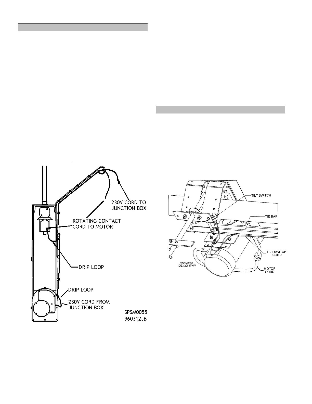
71 Run cord(s) from rotating contact up center
hanger and out to end of cord hanger alongside
3-wire cord from primary carriage junction box,
leaving drip loop near rotating contact. Figure 28.
Figure 28 - Cord Placement on Center Hanger
72 Connect rotating contact cord plug to plug on
appropriate cord coming from “A” or “S” motor
on primary carriage. See Figure 30 on page 27
for cord connection diagrams.
73 On 3-auger, single phase and 4- and 5-auger
units: Connect second rotating contact cord plug
to plug on cord from appropriate satellite
carriage motor. Figure 30, page 27.
74 Secure rotating contact cord(s) to cord hanger
and center hanger using provided black zip ties
as in step 57.
75 Connect plugs on short cord on “A” or “S” motor
to short cord on primary junction box. Figure
30, page 27.
76 On multiple-carriage units: Connect motors
using plugs on appropriate cords. Figure 30,
page 27.
XI. Wiring Tilt Switches on Motors
For part numbers and descriptions of parts
referenced in this section, see parts assembly
manual, page 53.
77 On multiple-carriage units: Connect:
2 black wires with male spades on satellite
carriage tilt switches to
Black and white wires with female spades at
one end of provided black tilt-switch cord.
Figure 29.
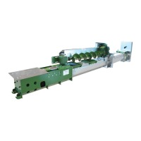
Figure 29 - Bottom, Angle View of Satellite Carriage Tilt
Switch Wiring
78 Run black motor cord(s) from step 76 and black
tilt-switch cord though plastic cord holders (see
Figure 11 on page 14 for plastic cord holder and
cord support strap placement).
79 Run cords together across tie bar to primary
carriage, securing out of way of moving parts
using provided black zip ties. Figure 29.
79.1 Note: Leave enough slack in cords that
carriages can travel entire length of
crosstube.