Assembly & Installation
VIII. Installing & Adjusting Reversing Mechanism
For part numbers and descriptions of parts referenced in this section, see parts assembly manual, page 53.
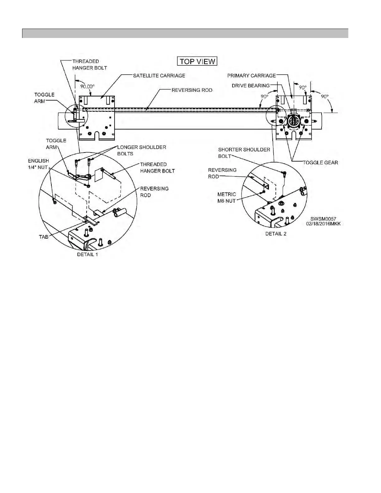
Figure 25 - Reversing Mechanism Installation and Adjustment
48 Ensure reversing mechanism (located on inside
top of primary carriage) is timed properly by
tripping reversing mechanism out of locking
position and moving toggle gears to a “centered”
position. Figure 25.
48.1 Note: In centered position, all components
should be parallel with edge of carriage
and each other. When timed properly,
reversing rod toggle gear (gear closest to
bin wall), drive bearing, and primary toggle
gear should all be perfectly parallel to
edge of carriage. Figures 42, 43.
See page 33 for reversing mechanism
troubleshooting instructions.
49 On satellite carriage closest to bin wall, bolt
toggle arm from parts sack to top of tab
extending beyond carriage shell using a 5/16”
shoulder bolt and 1/4” locking nut. Ensure
toggle arm is parallel with edge of satellite
carriage while drive bearing is centered.
Figure 25, Detail 1.
50 Feed end of reversing rod with threaded bolt
hole through inside of satellite carriages and let
sit inside the carriage closest to bin wall. Figure
25, Detail 1.
50.1 Note: Hole-to-hole length of reversing rod
should be checked by consulting
appropriate tables on pages 15-18.
51 Bolt opposite end of reversing rod (without
threaded bolt hole) to bottom of reversing rod
toggle gear on primary carriage using 8 mm
shoulder bolt and 6 mm locking nut. Figure 25,
Detail 2.
51.1 Note: A standard 5/32" hex (Allen) wrench
will fit this metric shoulder bolt.
52 Screw threaded hanger bolt from parts sack into
threaded hole on reversing rod end closest to
bin wall until bolt holes on threaded hanger bolt
and toggle arm align. Figure 26.