Assembly & Installation
35 Remove cotter and clevis pins from holes on 1”
tube coupler attached to gearmotor shaft. Save
pins. Figure 20.
36 Slide 1” tube coupler onto crosstube shaft and
insert 1/4” x 1-3/4” clevis pin and 1/16” x 3/4”
cotter pin from step 35 into holes to connect
crosstube shaft and gearmotor. Figure 20.
37 Insert 5/16” x 3/4” bolts and 5/16” lockwashers
from step 34 through holes in center hanger and
screw into holes on gearmotor. Check vertical
alignment. Tighten using 1/2” wrench. Figure 20.
38 Adjust gearmotor placement so no binding exists
on pins and center hanger and so pillow block
and center hanger do not touch tube. DO NOT
ATTEMPT TO ADJUST gearmotor shaft by
tapping on shaft with a hammer.
39 Tighten 4 set screws in pillow block bearing (2 on
each end) using 1/8” hex (Allen) wrench. Tighten
bolts (step 33) using 9/16” wrench. Tighten set
screws on pillowblock. Figure 20.
40 Screw hanger pipe tightly into 1” threaded hole
on cast electric junction box.
40.1 Note: Ensure threads are fully engaged,
as they will hold weight of Fastir.
Figure 20.
41 Slide cast bushing and brass washer onto hanger
pipe so they rest on junction box. Figure 20.
42 Slide end of hanger pipe up through bottom of
hole in center hanger so junction box is inside
center hanger. Figure 20, Figure 21.
Figure 21 - Placement of Cast Electric Junction Box on
Center Hanger
42.1 Note: Do not thread rotating contact
into cast electric junction box until
machine is raised in bin (see page 31
for rotating contact instructions).
Failure to heed this note can result in
rotating contact binding and breaking.
43 Slide channel hanger over hanger pipe. Figure
20, Figure 21.
44 Screw coupling onto hanger pipe ensuring tab
on coupling fits in slot on channel hanger.
Figure 20, Figure 21.
45 Thread a liquid-tight elbow (not provided) into
top of coupling. Ensure threads are seated
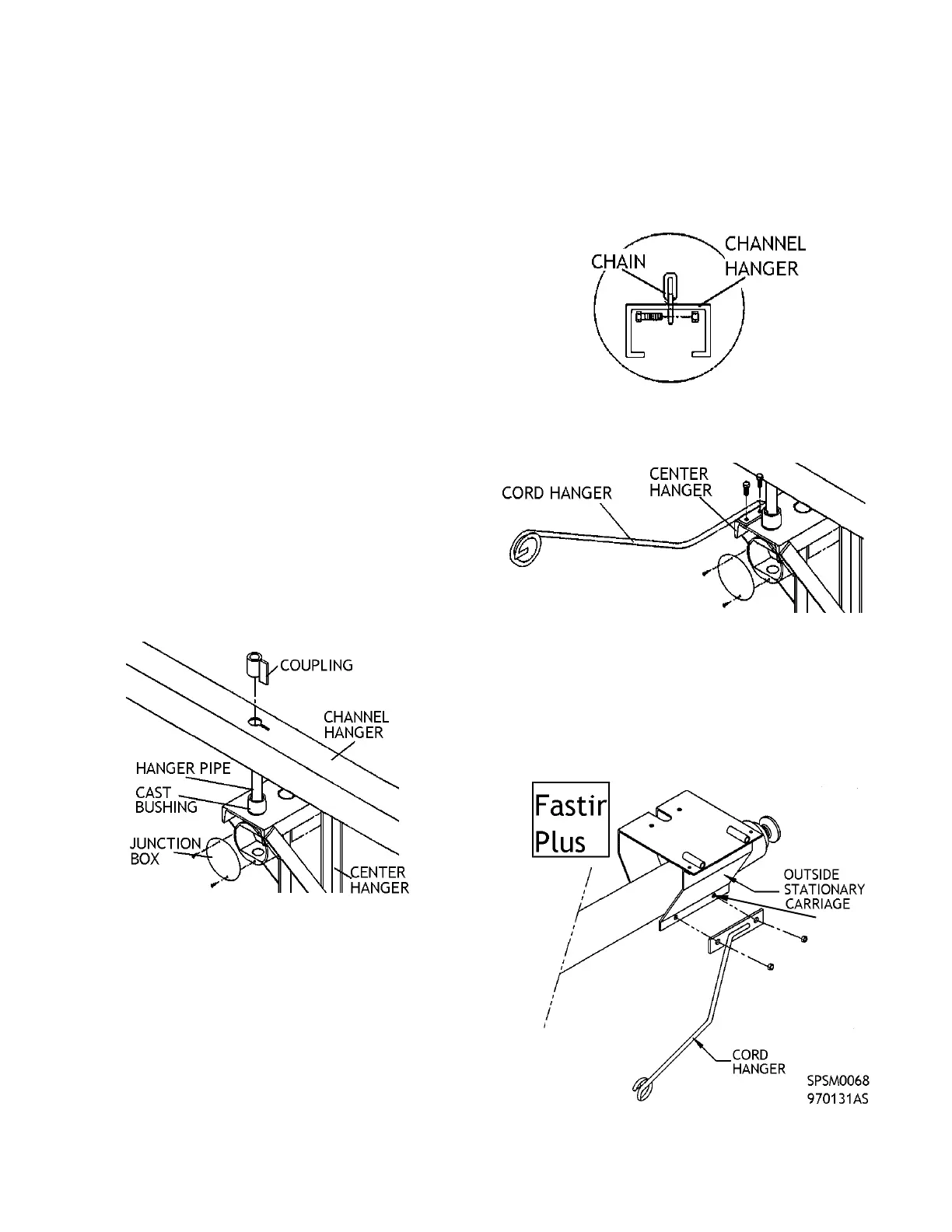
properly and tighten well. Figure 20.
46 Bolt chains onto each end of channel hanger
using 3/8” x 1” bolt and 3/8” nut. Tighten using
9/16” wrench. Figure 20, Figure 22.
46.1 Note: Center hanger will hang slightly tilted.
This is normal.
Figure 22 - Chain Placement in Channel Hanger
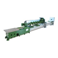
47 Bolt cord hanger to top of center hanger with 5/16” x
1” bolts. Tighten using 1/2” wrench. Figure 23.
Figure 23 - Cord Hanger Placement on Machine
47.1 Fastir Plus Only: Bolt cord hanger to
bottom plate of stationary outside carriage
using existing 1/2” carriage tightening
bolts (double nut). Figure 24.
47.2 Note: Position cord hanger behind
direction of travel of crosstube to keep
cords away from augers.
Figure 24 - Cord Hanger Placement on Fastir Plus Unit
EXISTING 1/2"
CARRIAGE
BOLT