24
Keep the manual for future reference - For more information visit www.sulzer.com
- Install pressure relief valve (s);
- Install an upstream pressure relief surge anticipating control valve);
- Install expansion crates (tanks) when needed.
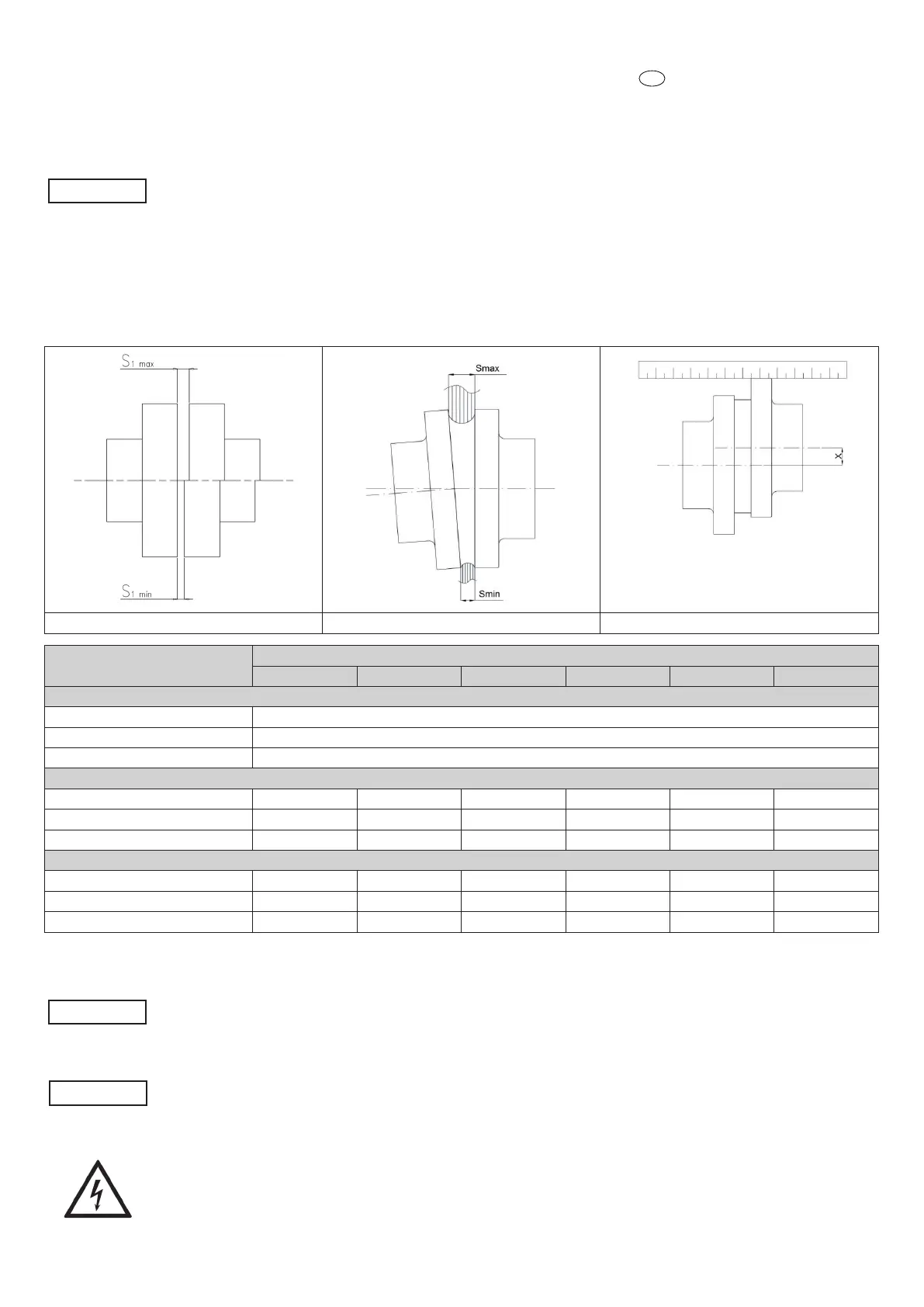
ALIGNEMENT
WARNING!
Although the group has already been fully aligned before shipment, it is necessary to check and recalibrate the alignment after having
installed the complete set.
- Remove the coupling guard.
- Check the axial alignment, it must be within the limits (S1 max / S1 min).
- Check the angular alignment through a feeler gauge: the angular displacement has to be measured as the dierence of the gap between the two half
coupling (S max - S min)
- Check the radial displacement of the two semi-couplings by using a bracket or a comparator (x).
- If necessary, correct the angle alignment by moving the motor (through the use of the shims or, through the adjustment screws placed in the feet of
the motor, if equipped).
- When the alignment is completed, replace the coupling guard.
Axial misalignment Angular misalignment Radial misalignment
Ø Coupling diameter [mm]
1/min
750 1000 1500 1800 3000 3600
Axial misalignment [mm]
≤ 145 S
1max
=4 ; S
1min
=2
145 ÷ 250 S
1max
=6 ; S
1min
=2
≥ 250 S
1max
=8 ; S
1min
=3
Angular misalignment (S
max
- S
min
) [mm]
≤ 145 0,25 0,2 0,2 0,15 0,15 0,1
145 ÷ 250 0,35 0,3 0,25 0,2 0,2 0,15
≥ 250 0,45 0,4 0,3 0,25 0,25 0,2
Radial misalignment x [mm]
≤ 145 0,25 0,2 0,2 0,15 0,15 0,1
145 ÷ 250 0,35 0,3 0,25 0,2 0,2 0,15
≥ 250 0,45 0,4 0,3 0,25 0,25 0,2
* This table is valid only for couplings with dowels supplied by Sulzer. For other types of coupling or for couplings not supplied by Sulzer, refer to the
specic technical documentation.
WARNING!
Do not use the pump without the properly coupling guard, installed in the appropriate way.
The coupling guard and coupling must not touch each other.
AUXILIARY CONNECTIONS
WARNING!
Verify the presence and proper installation of the necessary auxiliary connections.
ELECTRICAL CONNECTIONS
The connection to the power grid must be done in the respect of the local and national standards of the electric system of the place
where the pump is installed.
Furthermore, respect the connection diagrams supplied with the motor and with the control panel.
Perform the earth connection before all the other connections.
Verify the correct operation of the electric equipment (control panel etc…).
- Translation of the original instructions
EN
 Loading...