SUMAVISION EMR Operation Introduction
5 /53
LCD button to display IP and subnet mask information of the device, press and hold the
LCD button to display current alarm information of the device.
2.2.3 Keyboard Operating
User can enable the LCD panel through keyboard to view the IP of the device.
2.2.4 Connector of the Device
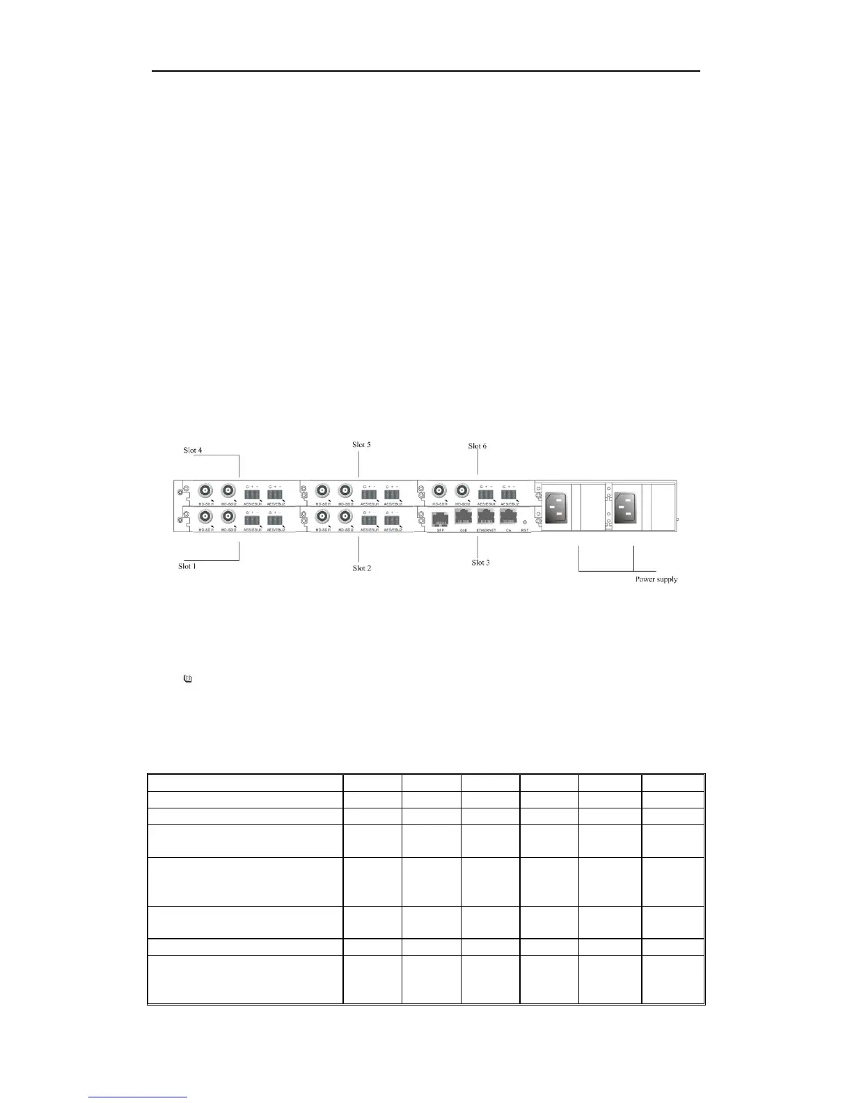
SUMAVISION EMR rear panel adopts the form of sub-panels. 6 slots formed with 6
sub-panels can be handled independently, which can facilitate the plugging and
un-plugging of sub-cards. Ground terminal, power switch are placed on the rear panel,
see Fig. 2-4 Appearance of SUMAVISION EMR rear panel.
Definition of slot: lower left Slot 1; lower center Slot 2; lower right Slot 3; upper left Slot 4;
upper center Slot 5; upper right Slot 6.
Fig. 2-5 Appearance of SUMAVISION EMR Rear Panel
The corresponding relationship between the function board and the slot used is shown in
Table 2-1 Function board and the slot used.
=======================================
User can select to read relevant part of the Instructions according to the function
board/card purchased.
=======================================
Table 2-2 Function board and the slot used