SUMAVISION EMR Operation Introduction
8 /53
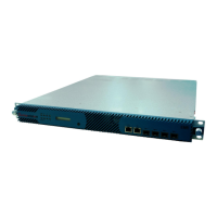
Fig. 2-12 4-frequency DVB-S2 Demodulation Receiving Card
2.2.5.8 Power socket
EMR provides two power sockets on the rear panel. The device will be powered on if the
power lead is insert the power socket correctly.
The power sockets used by EMR fully conform to the international industrial standards, for
detailed information, refer to Table 10-3 Power Socket Parameters.
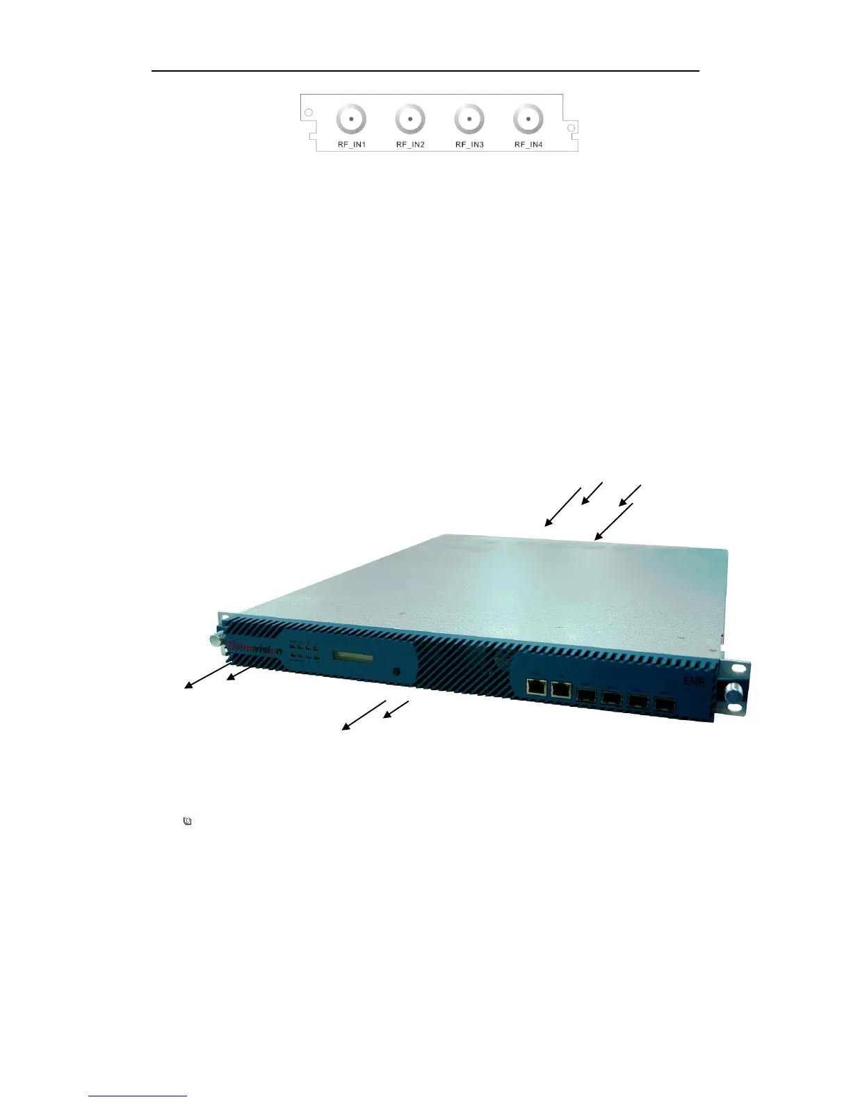
2.3 Heat Emission Descriptions
There are two exhaust fans installed inside the EMR to lower the risen temperature
caused by the working chips during the operation of the device.
EMR exhaust flow is shown as Fig.2-13 Exhaust Diagram.
Fig. 2-13 Exhaust Diagram
=======================================
Do not block the exhaust channel when installing the device.
=======================================
2.4 Control Descriptions
The integrated media processing platform-- SUMAVISION EMR can achieve the control
through Web and SNMP network management system.