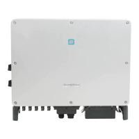
38
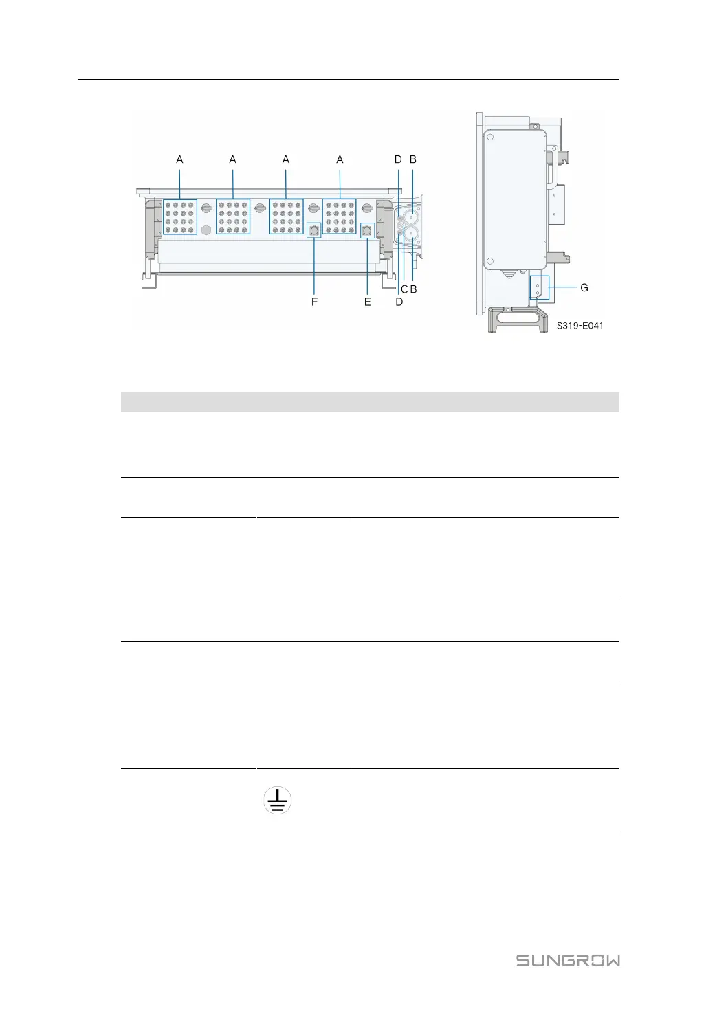
figure 5-2 Terminal Description (Two Wires per Phase with Multi-core Cable)
* The image shown here is for reference only. The actual product received may differ.
Item Terminal Mark Note
A PV terminals + / -
24 / 28 / 32, PV connector
The number of PV terminals varies, subject to
actual product received
B
AC wiring
terminal
—
Used for AC output cable connection.
C
Standby
grounding
terminal
—
If the PE cable is an independent single-core
cable, it should be led into the AC junction box
for cable wiring through the standby grounding
terminal
D
Tracker
terminal
—
Used for internal Tracker,Tracker power wir-
ing to power the Tracker.
E
Communica-
tion terminal
COM1
For RS485 communication wiring.
F
Communica-
tion terminal
COM2
Optional, digital input / output DI / DO and CAN
wiring, etc
Communication terminal COM2 is optional,
subject to actual product received
G
External
grounding
terminal
For reliable grounding
2, use at least one of them to ground the
inverter.
5.3 Electrical Connection Overview
Electrical connection in the PV system includes external grounding connection, AC connec-
tion, and PV string connection.
5 Electrical Connection User Manual