64
Protection devices required between the inverter and the tracking system control
box: disconnector switch (≥ 800 Vac) + fuse (16A, gM).
Length of the cable connecting the internal wiring terminal of the inverter and the
fuse should be less than 2.5 m.
5.9 RS485 Connection(COM1)
5.9.1 Interface Description
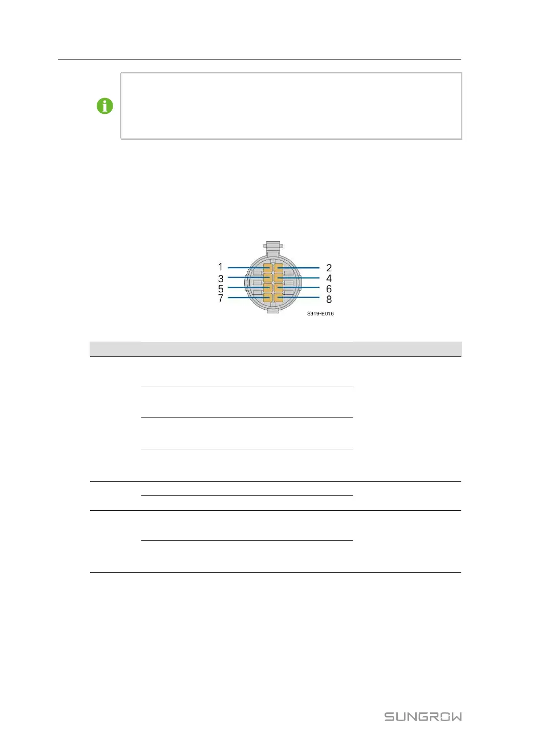
The inverter communication terminal COM1 is located at the bottom of the inverter, as
shown in the figure below.
table 5-5 Communication terminal COM1 definition
Port PIN Definition
Description
RS485_1
1
RS485A IN, RS485 differential sig-
nal+
Used for cascading in-
verters or connecting to
devices such as the Da-
ta Logger.
2
RS485A IN, RS485 differential sig-
nal+
3
RS485B OUT, RS485 differential
signal-
4
RS485B OUT, RS485 differential
signal-
PE
5
PE, shielding ground
—
6
PE, shielding ground
RS485_2
7
RS485A, RS485 differential signal
+
Communication device
for connection to the
tracking system
8
RS485B, RS485 differential
signal-
5.9.2 RS485 Communication System
Single-inverter Communication System
In case of a single inverter, communication cable connection requires only one RS485 cable.
5 Electrical Connection User Manual