6
2.2.2 Appearance
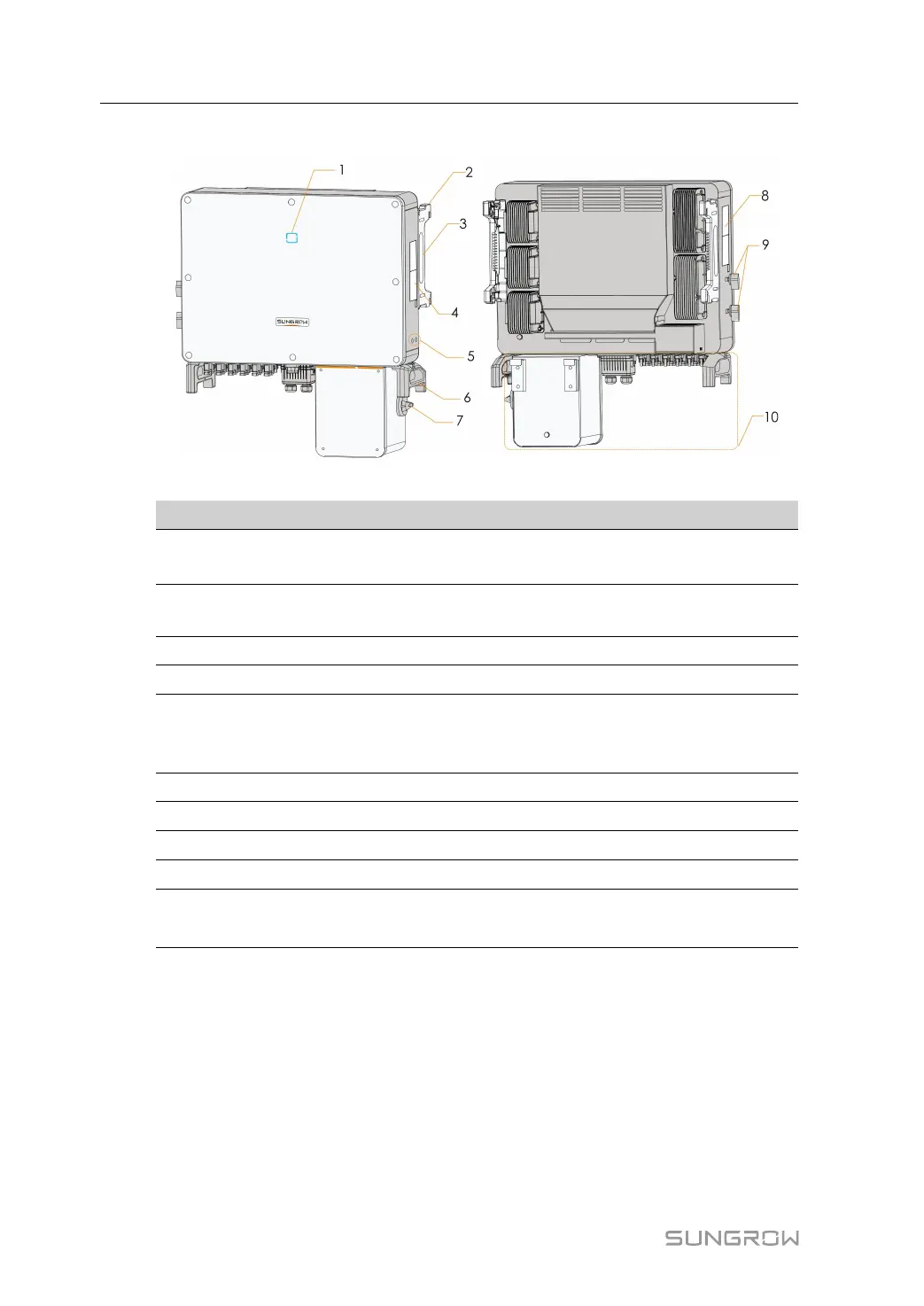
*The image shown here is for reference only. The actual product you receive may differ.
NNoo.. NNaammee
DDeessccrriippttiioonn
1
LED indicator
panel
HMI interface to indicate the present working state of the
inverter.
2
Mounting ears
4PCS, used to hang the inverter onto the mounting-
bracket.
3 Side handles
2PCS, used to move the inverter.
4 Labels
Warning symbols.
5
Additional
grounding
terminals
2PCS, use at least one of them to ground the inverter.
6 Bottom handles
2PCS, used to move the inverter.
7 AC switches
To disconnect the AC power from grid safely.
8 Labels
Nameplate, and QR code.
9 DC switches
To disconnect the DC power from PV safely.
10
Wiring area
AC terminals, DC terminals, and communication terminals.
For details, refer to 5-2. Terminal Description.
2 Product Introduction User Manual
 Loading...