15
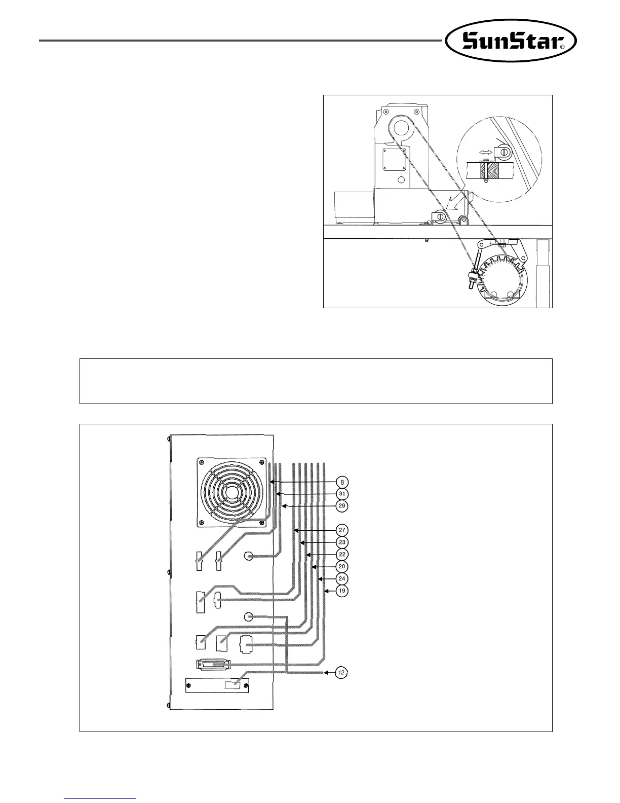
[ Fig. 8 ]
H. Method of Cable Connection
① SPS/B-1306(1507)
Power Supply Cable
Main Motor Cable
Encoder Cable
Step Motor Cable
Air Pressure Control Cable
Pedal Input Cable
Sensor Input Cable
Solenoid Output Cable
Operation Cable
Serial Communication Cable
Green
Backside of Control Box
※ The number in parentheses indicates cable number.
See the Electric Connection Wiring Diagram.
[ Caution ]
① Please turn off the power when you insert or pull out the cable connector.
② Please make sure that cable should not contact to machine parts.
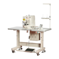
[ Fig. 7 ]
G. As seen in the Fig. adjust the position of idler to
adjust the tension of belt. (A Series)
Idler
 Loading...