8 • Questions? Call or Text +1-801-658-0015
Users Guide
What’s in the Box
• Pico DC Welder
• 90-250VAC Power Cord
• Foot Pedal
• Users Guide
• Safety Guide
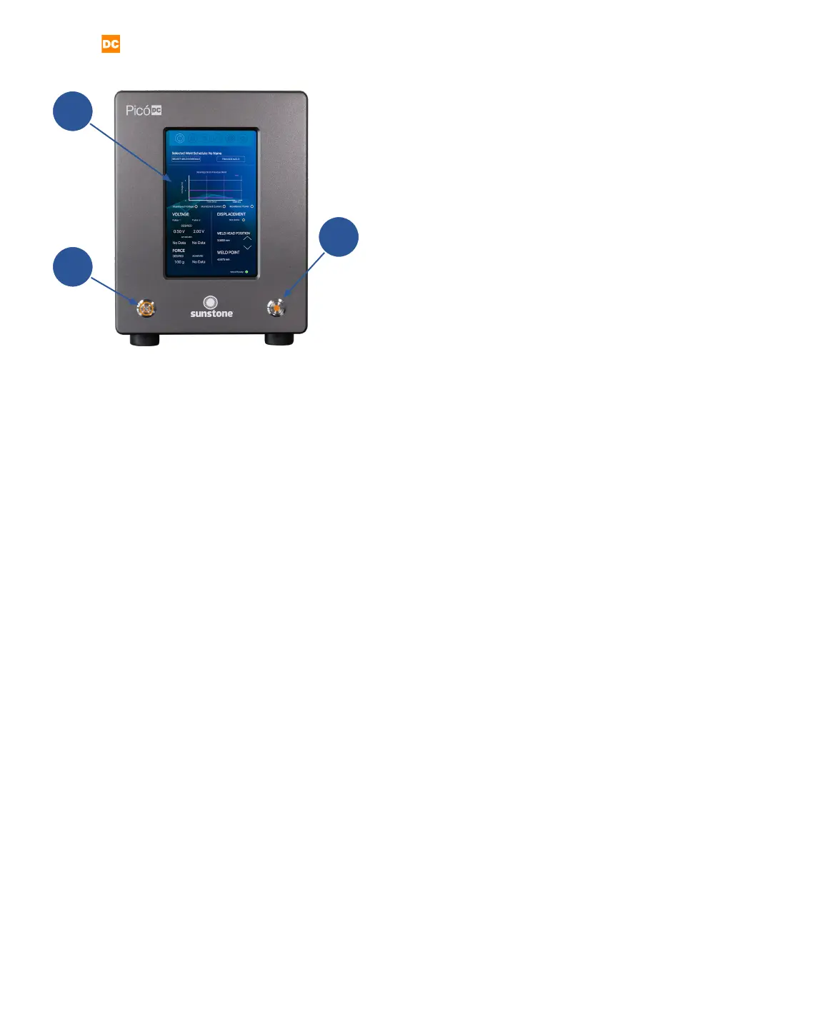
Exploring the Welder’s Front Panel
The front of the welder (see gure 8.1) consists of three
components: the digital Touchscreen (A), the Power
Button (B), and the Weld On/O Button (C).
Touchscreen
The digital touchscreen (A) displays the graphical user
interface and allows the operator to make changes to
the welding parameters. Every interaction with the weld
settings will happen via the touchscreen.
Power Button
The Power Button (B) will turn the welder on and o.
When turned on, the button will latch and stay de-
pressed. To turn the welder o, press the button again
to unlatch it and start the power down sequence.
Warning: Do NOT turn the welder o during boot up.
Allow the welder to complete the boot process before
turning the welder o.
The Weld On/O Button (C) can be used any time the
welder is powered on. When pressed, the button will
illuminate and stay depressed, allowing the welder to
make welds. When o, the touchscreen remains fully
functional, but no welds can be triggered (no energy
can be released). The weld on/o button allows oper-
ators to safely make changes to welding electrodes,
weld heads, and hand attachments. Operators can also
perform ‘dry runs’ to test timing, delays, and automa-
tions without releasing any weld energy.
A
B
C
Figure 8.1. The front panel of the Pico
includes the Touchscreen (A), the Power
Button (B), and the Weld On/O Button (C).