Questions? Call or Text +1-801-658-0015 • 5
e Micro Welder Experts
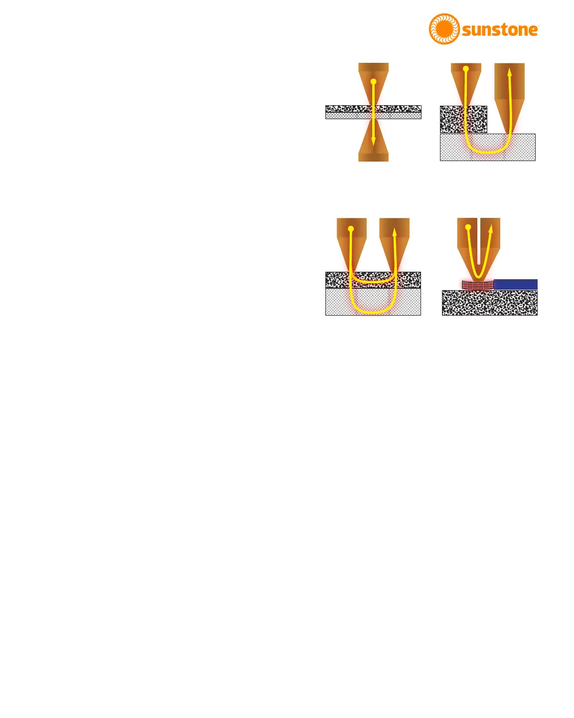
Direct weld (Opposed)
Current passes from one electrode through both
workpieces and out the opposing electrode. Typically
the easiest conguration to achieve good weld nuggets
and strength. See Figure 5.1.
Step (Adjustable Gap)
The electrode is placed on both materials, but from the
same side. A step or adjustable gap electrode congu-
ration can be challenging when maintain proper pres-
sure at each electrode due to possibly uneven surface.
See Figure 5.2.
Series (Adjustable Gap/Fixed Gap)
The electrodes are placed on the surface material only.
Because the current is split between both materials,
sometimes this conguration requires more weld ener-
gy than a direct weld would. See Figure 5.3.
Thermocompression
In a thermocompression conguration, the current
does not pass through the materials being welded, but
rather the current passes through the electrode tip. A
thermocompression conguration is most useful for
coated surfaces like magnet wire. See Figure 5.4.
How to Maintain Repeatable Welds
Consistent weld results require a consistent and
repeatable process. A few suggestions for ensuring
repeatable welds include:
• Keep a weld logbook documenting the process
once a successful weld has been achieved. Try
to keep track of the following:
• Force applied
• Electrodes (tip size/shape, electrode
material, etc.)
Figure 5.1. Direct
(opposed) electrode
conguration.
Figure 5.2. Step
(adjustable gap) electrode
conguration.
Figure 5.3. Series
(adjustable gap/xed gap)
electrode conguration.
Figure 5.4. Thermocom-
pression electrode cong-
uration.