Questions? Call or Text +1-801-658-0015 • 9
e Micro Welder Experts
R
O
T
A
T
I
O
N
R
O
T
A
T
I
O
N
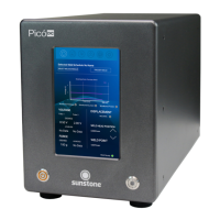
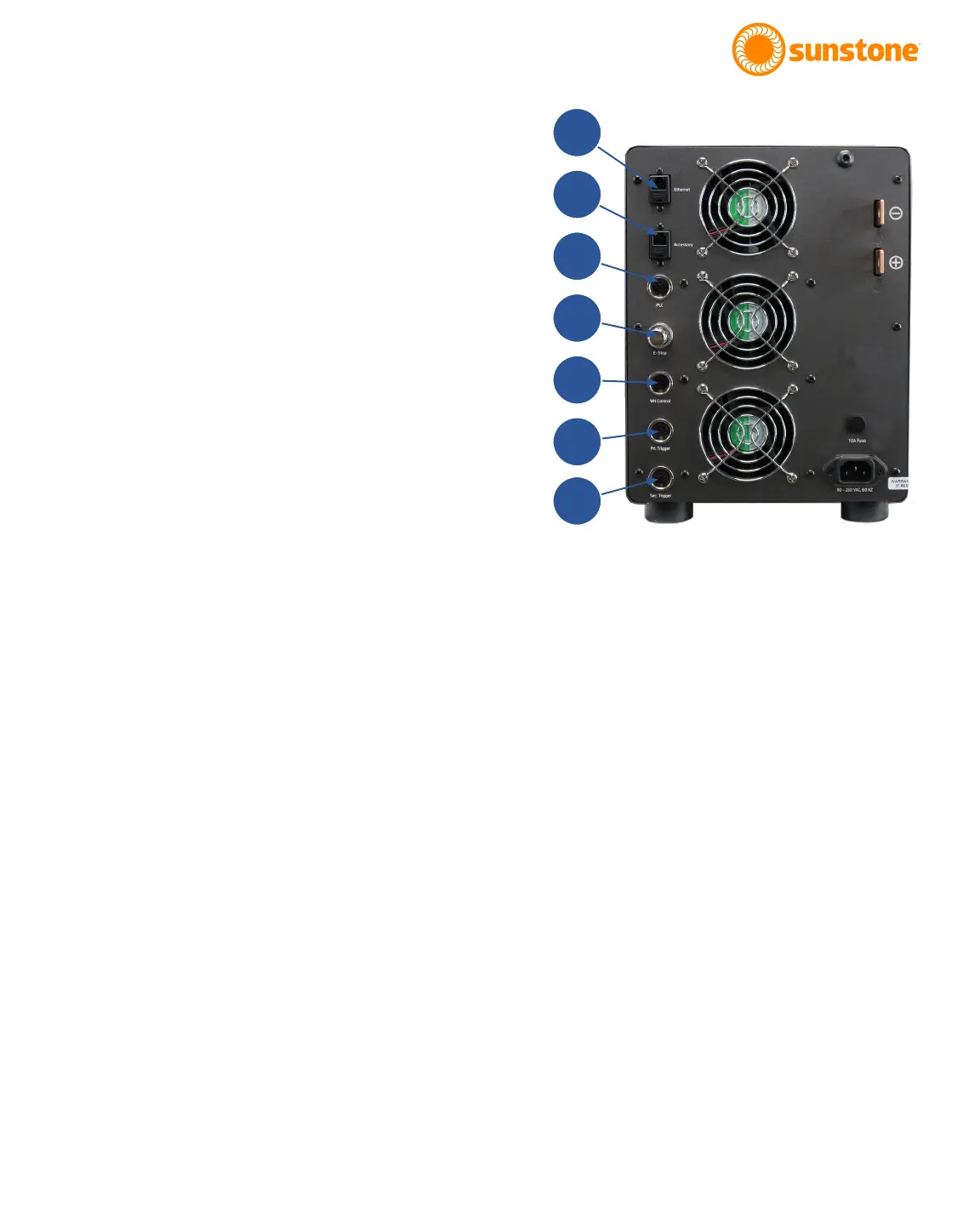
Figure 9.1. On the Pico’s back panel you’ll
nd all the ports, plugs, and connections
necessary to connect the Pico to a weld
head, foot pedal, power cables, and more.
Exploring the Welder’s Back Panel
On the back panel of the Pico you’ll nd identifying
details such as model and serial numbers as well as
certication marks. The following components can also
be found on the back panel, as shown in Figure 9.1 (see
also Appendix A, page 34 about connector pinouts):
Ethernet Port
The Ethernet Port (A) allows you to connect the Pico
to a computer network via an Ethernet connection, a
feature to be available in the future.
Accessory Port
The Accessory Port (B) is used to communicate with
external accessories such as the Micro E weld head.
PLC Port
The PLC Port (C) includes logic inputs and outputs that
can be used to communicate with a PLC.
E-Stop
The E-Stop Bypass Plug must be plugged into the unit
if you’re not using an E-Stop button. The E-Stop (D)
circuit is normally open and engaged. To disengage it is
necessary to close the circuit (in other words, if nothing
is plugged into this port, the E-Stop is engaged). If the
Power Button and Weld On/O Button are not illumi-
nated, but the display is on, the E-Stop is activated and
must be disengaged before the Pico will operate. Pinout
information can be found in Appendix A on page 34.
Weld Head Control
At time of press, the Pico does not use the Weld Head
Control Port (E). Rather the weld held is connected
using the Accessory Port (B).
Primary Trigger
Use the Primary Trigger Port (F) to connect an analog
foot pedal, or other switch, to the Pico to initiate a weld.
A
B
C
D
E
F
G