34 • Questions? Call or Text +1-801-658-0015
Users Guide
Appendix A: Pinout Details
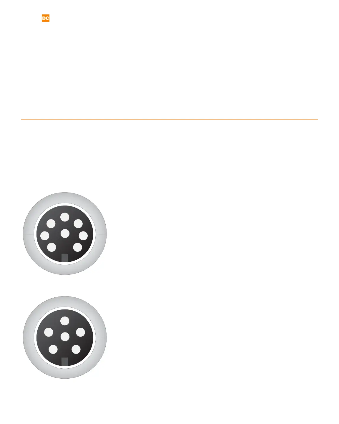
The following information details the Pico’s DIN connections, displayed here as if viewed from the pack panel.
Refer to Appendix A for pinout congurations.
1
2
3
4
5
6
7
8
PLC
The PLC port (see Figure 34.1) mates to SD-80LP, used to connect
PLC for basic functions, such as the following:
1 GND/Shield
2 +12V Current Limited
3 PLC Input 1. Short this pin with Pin1/GND to trigger an action.
4 PLC Input 2. Short this pin with Pin1/GND to trigger an action.
5 Weld Ready. Pull this pin up to +12V by connecting it with Pin
2/+12V. Signal will go low 0V, when weld is ready.
6 Alarm. Pull this pin up to +12V by connecting it with Pin
2/+12V. Signal will go low 0V, when alarm has occurred.
7 PLC Output 1. Pull this pin up to +12V by connecting it with
Pin 2/+12V. Signal will go low 0V, when this output has been
enabled.
8 PLC Output 2. Pull this pin up to +12V by connecting it with
Pin 2/+12V. Signal will go low 0V, when this output has been
enabled.
E-Stop
The E-Stop port (see Figure 34.2) mates to SD-60 LP, used to con-
nect an E-stop Switch or bypass.
1 GND/Shield
2 & 3 Normally open; ESTOP enabled. Close circuit to disable ES-
TO P.
4-6 Not Used
1
2
3
4
5
6
Figure 34.1. PLC pinout diagram.
Figure 34.2. E-Stop pinout diagram.