Questions? Call or Text +1-801-658-0015 • 35
e Micro Welder Experts
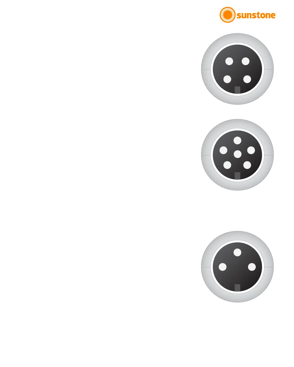
WH Control
The WH Control port (see Figure 35.1) mates to SD-40LP. At time
of publication, this port is not congured; could be used to control
pneumatic head with future upgrade.
1 GND/Shield
2 Weld Head Actuation 1. +12VDC(0.5A Max) is sent when weld
head needs to actuate.
3 Weld Head Actuation 2. +12VDC(0.5A Max) is sent when weld
head needs to actuate.
4 GND/Shield
Primary Trigger
The Primary Trigger port (see Figure 35.2) mates to SD-50LP, con-
nects to analog foot pedal.
1 Variable Foot Pedal. Connect this to Pin5/+12VDC with a
10Kohm potentiometer.
2 Primary Trigger. Connect this pin3/GND when trigger is de-
sired.
3 GND/Shield
4 Secondary Trigger. Connect this pin3/GND when trigger is
desired.
5 +12VDC limited
6 Not Used
Secondary Trigger
The Secondary Trigger port (see Figure 35.3) mates to SD-30LP,
connects to normal foot pedal
1 Not Connected
2 Primary Trigger. Connect this pin3/GND when trigger is de-
sired.
3 GND/Shield
1
2 3
4
Figure 35.1. WH Control pinout
diagram.
Figure 35.2. Primary Trigger pinout
diagram.
1
2
3
4
5
6
1
2
3
Figure 35.3. Secondary Trigger pinout
diagram.