Chapter 5: Advanced Motherboard Setup
5-13
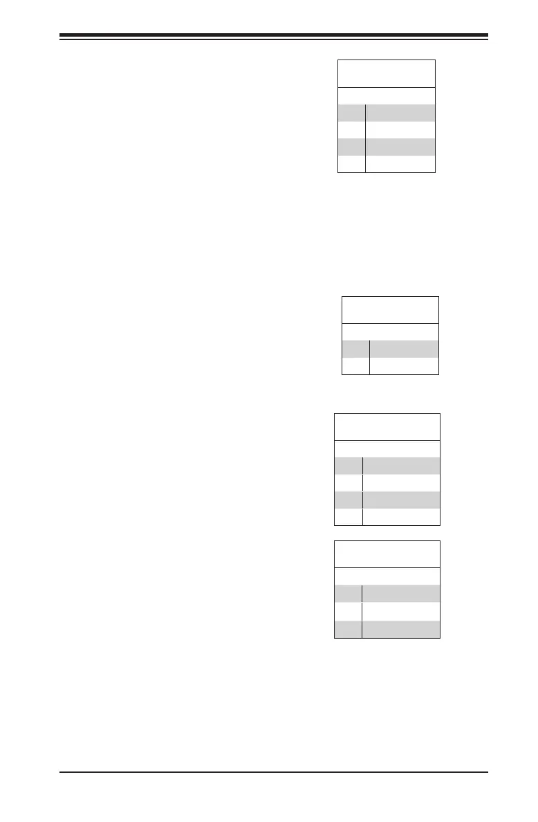
Fan Header
Pin Denitions
Pin# Denition
1 Ground (Black)
2 +12V (Red)
3 Tachometer
4 PWM_Control
Fan Headers
There are three fan 4-pin headers.
Pins 1-3 are backward compatible
with the traditional 3-pin fans, but you
can use 4-pin fans to take advantage
of the fan speed control using Pulse
Width Modulation through the BMC.
This allows the fan speeds to be auto-
matically adjusted based on the moth-
erboard temperature. Refer to the
table on the right for pin denitions.
Chassis Intrusion
A Chassis Intrusion header is located
at JL1 on the motherboard. Attach the
appropriate cable from the chassis to
inform you of a chassis intrusion when
the chassis is opened.
Chassis Intrusion
Pin Denitions (JL1)
Pin# Denition
1 Intrusion Input
2 Ground
DOM PWR Connector (JSD1)
The Disk-On-Module (DOM) power
connector, located at JSD1, provides
5V power to a solid-state DOM storage
device connected to one of the SATA
ports. See the table on the right for
pin denitions.
DOM PWR
Pin Denitions
Pin# Denition
1 5V
2 Ground
3 Ground
System Management Bus Header
A System Management Bus header
for IPMI 2.0 is located at JIPMIB1.
Connect the appropriate cable here
to use the IPMI I
2
C connection on
your system.
SMBus Header
Pin Denitions
Pin# Denition
1 Data
2 Ground
3 Clock
4 No Connection

 Loading...


