Chapter 5: Advanced Serverboard Setup
5-17
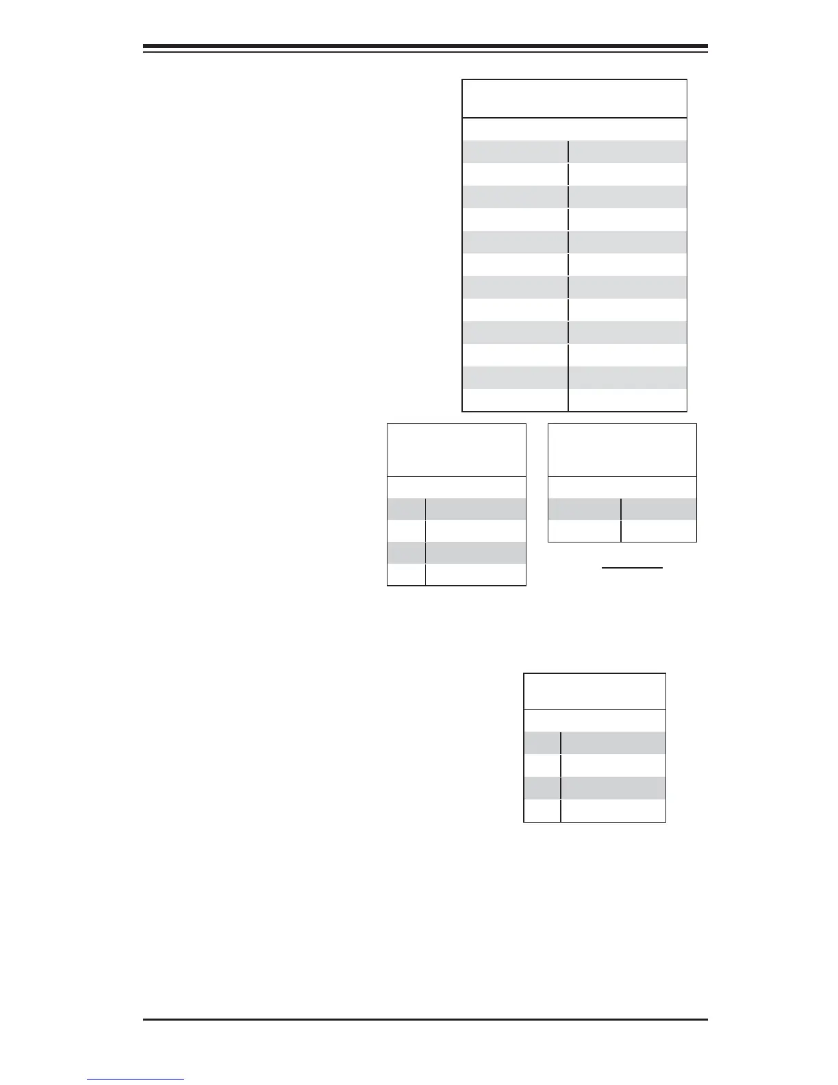
Power Connectors
A 24-pin main power supply connector
(JPWR1), two 8-pin CPU power
connectors (JPWR2/JPWR3), and a
4-pin Auxiliary power connector (JPWR4)
are located on the motherboard. These
power connectors meet the SSI EPS 12V
specifi cation and must be connected to
your power supply to provide adequate
power to the system. See the tables on
the right for pin defi nitions.
ATX Power 24-pin Connector
Pin Defi nitions (JPW1)
Pin# Defi nition Pin # Defi nition
13 +3.3V 1 +3.3V
14 -12V (NC) 2 +3.3V
15 COM 3 COM
16 PS_ON 4 +5V
17 COM 5 COM
18 COM 6 +5V
19 COM 7 COM
20 Res (NC) 8 PWR_OK
21 +5V 9 5VSB
22 +5V 10 +12V
23 +5V 11 +12V
24 COM 12 +3.3V
(Required)
12V 8-pin
Power Connector Pin
Defi nitions
Pins Defi nition
1 through 4 Ground
5 through 8 +12V
4-pin
Power Connector
Pin Defi nitions
Pin# Defi nition
1 +12V
2 Ground
3 Ground
4 +12V
Fan Headers
This motherboard has 11 system/cooling
fan headers (FAN1-FAN7, FANA-FAND)
on the motherboard. FAN6 is for CPU1,
and FAN7, for CPU2. All these 4-pin
fan headers are backward compatible
with the traditional 3-pin fans. However,
fan speed control is available for 4-pin
fans only. The fan speeds are controlled
by Thermal Management via IPMI 2.0
interface. See the table on the right for
pin defi nitions.
Fan Header
Pin Defi nitions
Pin# Defi nition
1 Ground
2 +12V
3 Tachometer
4 PWR Modulation

 Loading...