Chapter 5: Advanced Serverboard Setup
5-23
5-8 Jumper Settings
Explanation of Jumpers
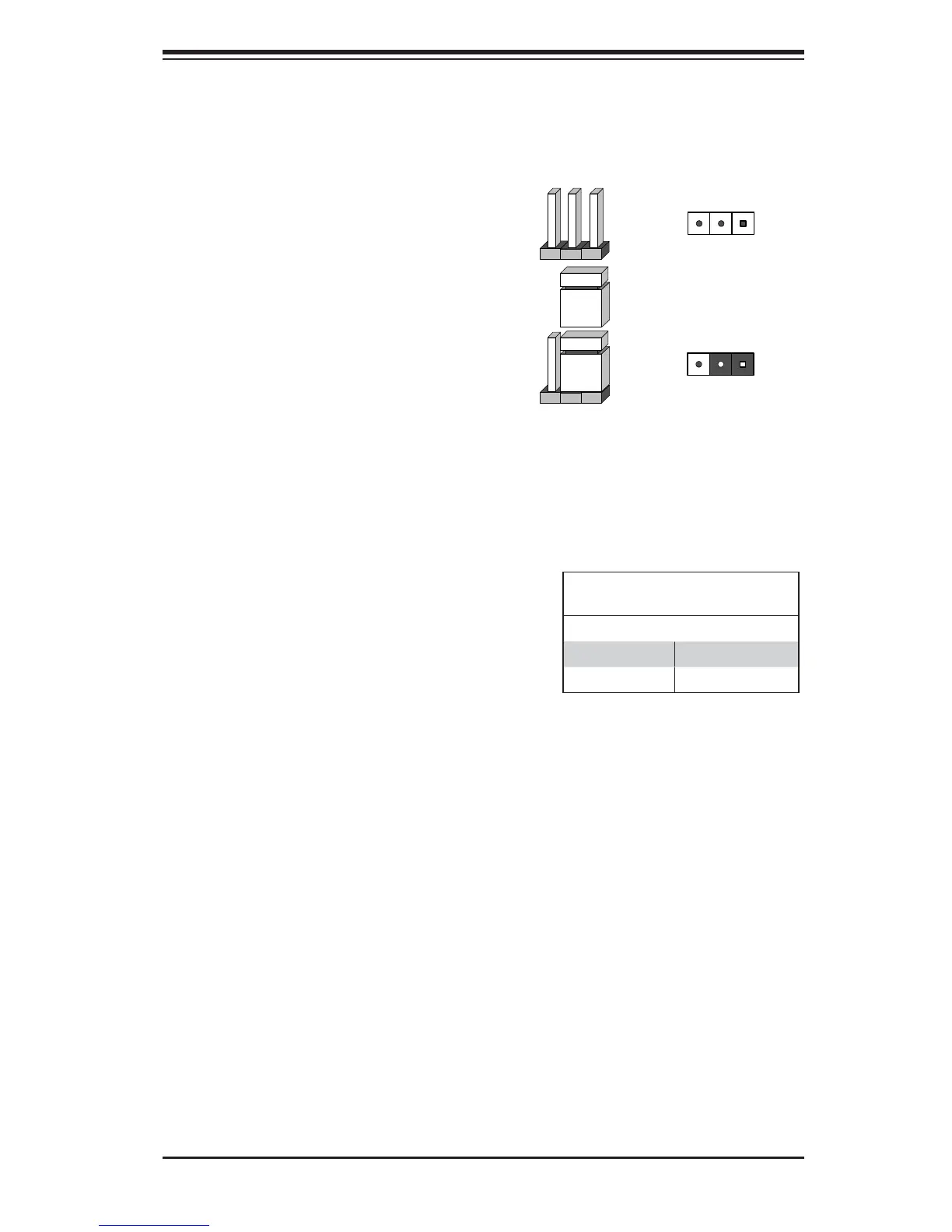
To modify the operation of the
serverboard, jumpers can be used
to choose between optional settings.
Jumpers create shorts between two
pins to change the function of the
connector. Pin 1 is identified with
a square solder pad on the printed
circuit board. See the diagram at right
for an example of jumping pins 1 and
2. Refer to the serverboard layout
page for jumper locations.
Note: On two-pin jumpers, "Closed"
means the jumper is on and "Open"
means the jumper is off the pins.
CMOS Clear
JBT1 is used to clear CMOS. Instead of pins, this "jumper" consists of contact pads
to prevent accidental clearing of CMOS. To clear CMOS, use a metal object such
as a small screwdriver to touch both pads at the same time to short the connection.
Note: Please completely shut down the system, and then short JBT1 to clear
CMOS.
Connector
Pins
Jumper
Setting
3 2 1
3 2 1
ME Manufacturing Mode Select
Close pins 2 and 3 of jumper JPME2
to bypass SPI flash security and
force the system to operate in the
Manufacturer (ME) mode, allowing
the user to fl ash the system fi rmware
from a host server for system setting
modifi cations. See the table on the
right for jumper settings.
ME Mode Select
Jumper Settings
Jumper Setting Defi nition
Pins 1-2 Normal (Default)
Pins 2-3 Manufacture Mode
Pin 1-2 short

 Loading...