5-10
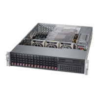
SuperStorage Server 2028R-NR48N
Figure 5-3. X10DSC+ Layout
5-5 Motherboard Details
Notes
Jumpers not indicated are for test purposes only and should not have their settings
changed.
Note that the PCI slots are enabled when their corresponding processors are
installed. "CPU2 Slot 4" indicates that the second CPU must be installed to the
CPU2 socket to enable this PCI slot.
" " indicates the position of pin 1.
S-SGPIO1
JI2C_FP1
JITP1
JPW3
JPW2
JPW1
FAN1
FAN2
FAN4FAN5
FAN3
JIPMB1
BIOS
LICENSE
BAR CODE
IPMI CODE
REV:1.01
X10DSC+
X16PCI-E 3.0CPU1 SIOM
S-SATA3
TPM/PORT80
USB2(3.0)
S-SATA0
S-SATA1
CPU2 SLOT1 PCI-E 3.0 X8
CPU2 SLOT2 PCI-E 3.0 X16
CPU2 SLOT3 PCI-E 3.0 X16
CPU-XDP
CPU1 JMEZZ1 PCI-E 3.0x8
IPMI_LAN
CPU2_MEMORY_LED
CPU1_MEMORY_LED
USB0/1(3.0)
P2-DIMME2
P2-DIMME1
P2-DIMME3
P2-DIMMF1
P2-DIMMF2
P2-DIMMF3
S-SATA2
UID
CPU2
P1_NVMe#0
P1_NVMe#1
P1_NVMe#2
VGA COM1
P1-DIMMA2
P1-DIMMA3
P1-DIMMB1
P1-DIMMA1
P1-DIMMB2
P1-DIMMB3
P1_NVMe#3
P1-DIMMD1
P1-DIMMD2
CPU1
P1-DIMMD3
P1-DIMMC1
P1-DIMMC2
P1-DIMMC3
P2-DIMMH3
P2-DIMMG3
P2-DIMMH1
P2-DIMMH2
P2-DIMMG1
P2-DIMMG2
JBT1
BMC_HB_LED1
BMC
BIOS
PCH
1
1
1
1
Battery
JUIDB2
X10DSC+ Quick Reference
Jumper Description Default Setting
JBT1 Clear CMOS/Reset BIOS Conguration See Section 5-8
JPB1 BMC Enable Pins 1-2 (Enabled)
JPG1 VGA Enable Pins 1-2 (Enabled)
JPME2 Manufacture (ME) Mode Select Pins 1-2 (Normal)
JWD1 Watch Dog Timer Enable Pins 1-2 (Reset)
 Loading...
