5-16
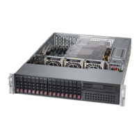
SuperStorage Server 2028R-NR48N
Fan Headers
There are ve fan headers on the
motherboard, all of which are 4-pin
fans. Pins 1-3 of the fan headers
are backward compatible with the
traditional 3-pin fans. (Fan speed
control is supported with 4-pin fans
only.) See the table on the right for
pin definitions. The onboard fan
speeds are controlled by Thermal
Management (via IPMI).
NMI Button
The non-maskable interrupt button
header is located on pins 19 and 20
of JF1. Refer to the table on the right
for pin denitions.
NMI Button
Pin Denitions
(JF1)
Pin# Denition
19 Control
20 Ground
Fan Header
Pin Denitions
(FAN1-8)
Pin# Denition
1 Ground (Black)
2 +12V (Red)
3 Tachometer
4 PWR Modulation
Power On LED
The Power On LED connector is
located on pins 15 and 16 of JF1. This
connection is used to provide LED
indication of power being supplied to
the system. See the table on the right
for pin denitions.
Power LED
Pin Denitions
(JF1)
Pin# Denition
15 3.3V
16 PWR LED
Chassis Intrusion
The Chassis Intrusion header is
designated JL1. Attach an appropriate
cable from the chassis to inform you of
a chassis intrusion when the chassis
is opened
Chassis Intrusion
Pin Denitions
Pin# Denition
1 Intrusion Input
2 Ground
Other Connectors
 Loading...
