Chapter 1: Overview
1-11
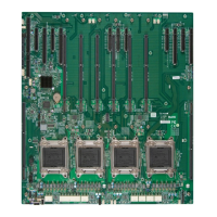
X10QBi Baseboard Quick Reference
X10QBi Jumpers
Jumper
Description Default Setting
JBT1
Clear CMOS See Chapter 3
JI
2
C1/JI
2
C2
SMB to PCI-E Slots Pins 2-3 (Disabled)
JPB1 (on the I/O module)
BMC Enabled Pins 1-2 (Enabled)
JPG1 (on the I/O module) VGA Enabled Pins 1-2 (Enabled)
JPME1 ME Mode Recovery Pins 1-2 (Normal)
JPME2 ME Mode Select Pins 1-2 (Normal)
JPL1 (on the I/O module) GLAN1/GLAN2 Enable Pins 1-2 (Enabled by con-
necting to the cable)
JPT1 TPM Enabled Pins 1-2 (Enabled)
JWD1 Watch Dog Pins 1-2 (Reset)
X10QBi Baseboard Connectors
Connectors Description
4-pin Fans 4-pin System/Cooling Fan Headers (FAN1-FAN10)
BT2 Onboard Battery (See Chpt. 3 for Battery Disposal)
COM1 (on the baseboard) Serial/COM Port Header 1 (on the X10QBi base-
board)
COM2 (on the I/O module) Serial/COM Part 2 (located on the AOM-X10QBi-A/L
I/O module)
I-SATA 0-5 Intel SATA Connectors 0-5
JD1 Speaker/Power LED Indicator
JF1 Front Panel Control Header
JIPMB1 4-pin External BMC I
2
C Header (for an IPMI Card)
JL1 Chassis Intrusion
JOH1 Overheat/Fan Fail LED
JPI
2
C1 Power Supply SMBbus I
2
C Header
JPW1 ATX 24-pin Power Connector
JPW2-JPW7 8-pin Power Connectors
JSD1 SATA-DOM (Device_on_Module) Power Connector
VGA1/2 (on the I/O mod-
ule)
VGA/Video Port1/Port2
LAN1/2 (on the I/O mod-
ule)
G-bit Ethernet Ports 1/2
IPMI_LAN (on the I/O mod-
ule)
(BMC) IPMI_LAN
SP1 Onboard Buzzer/Internal Speaker
 Loading...


