Chapter 1: Overview
1-5
JPME2 Management Engine (ME)
Manufacture Mode Select
Pins 1-2 (Normal)
JWD1 Watch Dog Pins 1-2 (Reset)
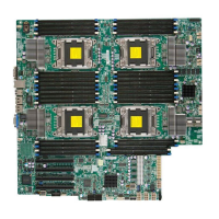
X9DRW-3F/X9DRW-iF Connectors
Connectors Description
COM1/COM2 Backplane COM Port1/Front Accessible COM2 Header
FAN1~4,FANA, FANB CPU/System Fan Headers
I-SATA 0~5 Intel PCH SATA Connectors 0~5
JBAT1 Onboard Battery (See Chpt. 3 for Used Battery Disposal)
JD1 Speaker/Power LED Connector (Pins 1~3: PWR LED, Pins
6~7: Onboard Buzzer/Pins 4~7: External Speaker)
JF1 Front Panel Control Header
JIPMB1 4-pin External BMC I
2
C Header (for an IPMI Card)
JL1 Chassis Intrusion
JLPC1 Port80 Header
JOH1 Overheat/Fan Fail LED
JPI
2
C1 Power Supply SMBbus I
2
C Header
JPW1 ATX 24-Pin Power Connector (See Warning on Pg. 1-6)
JPW2/3 12V 8-Pin Power Connectors (See Warning on Pg. 1-6)
JPW4 12V 4-Pin Power Connector (See Warning on Pg. 1-6)
JSD1 SATA DOM (Device_On_Module) Power Connector
JSTBY1 Standby Power Connector
LAN1/2 G-bit Ethernet Ports 1/2
(IPMI) LAN IPMI_Dedicated LAN
SATA/SCU 0~3, 4~7 Serial_Link SATA/SCU Connections 0~3, 4~7 (for X9DRW-
3F), SCU 0~3 (for X9DRW-iF)
SP1 Onboard Buzzer (Internal Speaker)
SXB1A SMC-Proprietary SPEC Slot (See Note 1 below.)
SXB1B SMC-Proprietary PCI-E 3.0 x16 + x16 Add-on Card Slot
(Left) (See Note 1 below.)
SXB1C SMC-Proprietary SPEC Slot (See Note 1 below.)
SXB2 SMC-Proprietary PCI-E 3.0 x16 Add-on Card Slot (Right)
(See Note 2)
Note 1: For SXB1A/SXB1B/SXB1C PCI-Exp. slots to work properly, please
use an SMC-proprietary riser card (eg. RSC-RIUW-2E16) in the slots.
Note 2: For SXB2 PCI-Exp. slot to work properly, please use the SMC-
proprietary riser card RSC-R2UW-2EBR or RSC-R1UW-E8R in the slot.

 Loading...


