1-12
Supermicro C7Z170-M/C7H170-M Motherboard User’s Manual
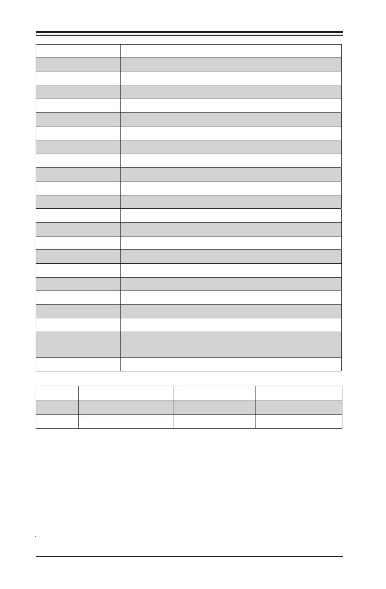
Connector Description
I/O Back Panel See Back Panel I/O Connectors, below right
Audio FP Front Panel Audio Header
BT1 Onboard Battery
COM1 COM1 Port Header
Fan 1,2,3,4,5 System/CPU Fan Headers (Fan1: CPU Fan)
JD1 Speaker/buzzer (Pins 1~4: External Speaker, Pins 3~4: Buzzer)
JF1 Front Panel Control Header
JL1 Chassis Intrusion Header
JLED1 Power LED Indicator Header
JPW1 24-pin ATX Main Power Connector (Required)
JPW2 +12V 8-pin CPU power Connector (Required)
JPW3 +12V 4-pin Peripheral Power Connector
JSD1 SATA DOM (Disk On Module) Power Connector
JSPDIF_OUT Sony/Philips Digital Interface (S/PDIF) Out Header
JSTBY1 Standby Power Header
SP1 Internal Speaker/Buzzer
I-SATA0~5 (Intel® Z170) Serial ATA (SATA 3.0) Ports 0~5 (6Gb/sec)
USB 2/3 Front Panel Accessible USB 2.0 Headers 2/3
USB 8/9 (3.1) Front Panel Accessible USB 3.1 Header 8/9
USB 10/11 (3.0) Front Panel Accessible USB 3.0 Header 10/11
PCI-E M.2 CONNECTOR PCI-E M.2 Connector, PCIe M.2 supports M-Key (PCIe3.0 x4) storage
card only.
JTPM1 Trusted Platform Module (TPM) Header
LED Description Color/State Status
LED1 Onboard Standby PWR LED Green: Solid on Power On
LED2 M.2 LED Green: M.2 on board M.2 on board

 Loading...


