Chapter 2: Installation
2-23
JBR1
JTBT1
JPW3
+
MH12
JSTBY1
JF1
JTPM1
S1
JAUDIO1
JPCIE1
JPCIE2
JD1
JUSBLAN1
JBT1
FAN4
FAN1
FAN2
FAN3
FAN5
S4
S8
S11
7
JUSB30_I4
19
JPW1
1
LED1
LED2
A
C
JPW2
JHD_AC1
JI2C2
JI2C1
JL1
JSPDIF_OUT
JSMB1
JLED1
JSMB2
JPUSB1
JPUSB2
1
JPL1
JPME2
JWD1
1
3
DESIGNED IN USA
C7Z170-M
REV:1.00
MAC CODE
BAR CODE
TP104
TP103
TP100
MH2
MH1
Power Button
BIOS Restore
CLEAR CMOS
JHD_AC1:Audio AC97 and HD audio jumper
3 PIN POWER LED
JLED1:
2-3:BIOS RECOVERY
1-2:NORMAL
JBR1:
USB 10/11(3.0)
USB 8/9(3.1)
USB 2/3
USB 4/5(3.0)
USB 6/7(3.0)
HDMI/DP
DVI
1-2 ENABLE
2-3 DISABLE
JPUSB2:USB 8/9 WAKE UP
1-2 ENABLE
2-3 DISABLE
JPUSB1:USB0/1 WAKE UP
PCH SLOT1 PCI-E 3.0 X1
JPAC1
5V STBY POWER
PCH SLOT2 PCI-E 3.0 X4
LAN
KB/MOUSE
JWD1:
JSD1:
LAN
DISABLE
ENABLE
2-3
1-2
JPL1
2-3:NMI
1-2:RST
WATCH DOG
CPU
2-3:ME MANUFACTURING MODE
/CPU FAN
USB 0/1
1-2:NORMAL
JPME2:
SATA DOM PWR
JTPM1:TPM/PORT80
JL1:
AUDIO FP
HDD PWR
LEDLED
CMOS CLEAR
DIMMB1
DIMMB2
NIC1
SPEAKER:1-4
JD1:
BUZZER:3-4
JI2C1/JI2C2
ON:ENABLE
OFF:DISABLE
NIC2
HD AUDIO
OH/FF
LED
CHASSIS INTRUSION
DIMMA1
DIMMA2
RST
PWR
JF1
ON
ALWAYS POPULATE RED SOCKET FIRST
UNB NON-ECC DDR4 DIMM REQUIRED
CPU SLOT3 PCI-E 3.0 X16
M.2 PCI-E X4
COM1
2-3:DISABLE
1-2:ENABLE
JPAC1:AUDIO
I-SATA2
I-SATA3
I-SATA1
I-SATA5
I-SATA0
I-SATA4
BT1
S/PDIF OUT
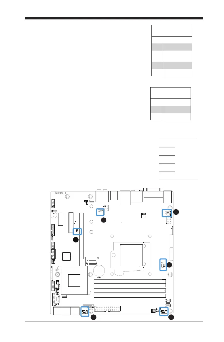
Fan Header
Pin Denitions
Pin# Denition
1 Ground (Black)
2 2.5A/+12V
(Red)
3 Tachometer
4 PWM_Control
Fan Headers (Fan 1 ~ Fan 5)
The C7Z170-M/C7H170-M has ve fan
headers (Fan 1~Fan 5). These fans are
4-pin fan headers. Although pins 1-3 of
the fan headers are backward compat-
ible with the traditional 3-pin fans, we
recommend the use 4-pin fans to take
advantage of the fan speed control. This
allows the fan speeds to be automatically
adjusted based on the motherboard tem-
perature. Refer to the table on the right
for pin denitions.
A
B
A. Fan 1 (CPU Fan)
B. Fan 2
C. Fan 3
D. Fan 4
E. Fan 5
F. Chassis Intrusion
C
D
E
Chassis Intrusion (JL1)
A Chassis Intrusion header is located at
JL1 on the motherboard. Attach the ap-
propriate cable from the chassis to inform
you of a chassis intrusion when the chassis
is opened.
Chassis Intrusion
Pin Denitions (JL1)
Pin# Denition
1 Intrusion Input
2 Ground

 Loading...


