2-22
Supermicro C7Z170-M/C7H170-M Motherboard User’s Manual
C
JBR1
JTBT1
JPW3
+
MH12
JSTBY1
JF1
JTPM1
S1
JAUDIO1
JPCIE1
JPCIE2
+
JD1
JUSBLAN1
JBT1
FAN4
FAN1
FAN2
FAN3
FAN5
S4
S8
S11
7
JUSB30_I4
1
19
JPW1
1
LED1
LED2
A
C
JPW2
JHD_AC1
JI2C2
JI2C1
JL1
JSPDIF_OUT
JSMB1
JLED1
JSMB2
JPUSB2
1
JPL1
JPME2
JWD1
1
3
DESIGNED IN USA
C7Z170-M
REV:1.00
MAC CODE
BAR CODE
TP104
TP103
TP100
MH2
MH1
Power Button
BIOS Restore
CLEAR CMOS
JHD_AC1:Audio AC97 and HD audio jumper
3 PIN POWER LED
JLED1:
2-3:BIOS RECOVERY
1-2:NORMAL
JBR1:
USB 10/11(3.0)
USB 8/9(3.1)
USB 2/3
USB 4/5(3.0)
USB 6/7(3.0)
HDMI/DP
DVI
1-2 ENABLE
2-3 DISABLE
JPUSB2:USB 8/9 WAKE UP
1-2 ENABLE
2-3 DISABLE
PCH SLOT1 PCI-E 3.0 X1
JPAC1
5V STBY POWER
PCH SLOT2 PCI-E 3.0 X4
LAN
KB/MOUSE
JWD1:
JSD1:
LAN
DISABLE
ENABLE
2-3
1-2
JPL1
2-3:NMI
1-2:RST
WATCH DOG
CPU
2-3:ME MANUFACTURING MODE
/CPU FAN
USB 0/1
1-2:NORMAL
JPME2:
SATA DOM PWR
JTPM1:TPM/PORT80
JL1:
AUDIO FP
HDD PWR
LEDLED
CMOS CLEAR
DIMMB1
DIMMB2
NIC1
SPEAKER:1-4
JD1:
BUZZER:3-4
JI2C1/JI2C2
ON:ENABLE
OFF:DISABLE
NIC2
HD AUDIO
OH/FF
LED
X
CHASSIS INTRUSION
DIMMA1
DIMMA2
RST
PWR
JF1
ON
ALWAYS POPULATE RED SOCKET FIRST
UNB NON-ECC DDR4 DIMM REQUIRED
CPU SLOT3 PCI-E 3.0 X16
M.2 PCI-E X4
COM1
2-3:DISABLE
1-2:ENABLE
JPAC1:AUDIO
I-SATA2
I-SATA3
I-SATA1
I-SATA5
I-SATA0
I-SATA4
BT1
S/PDIF OUT
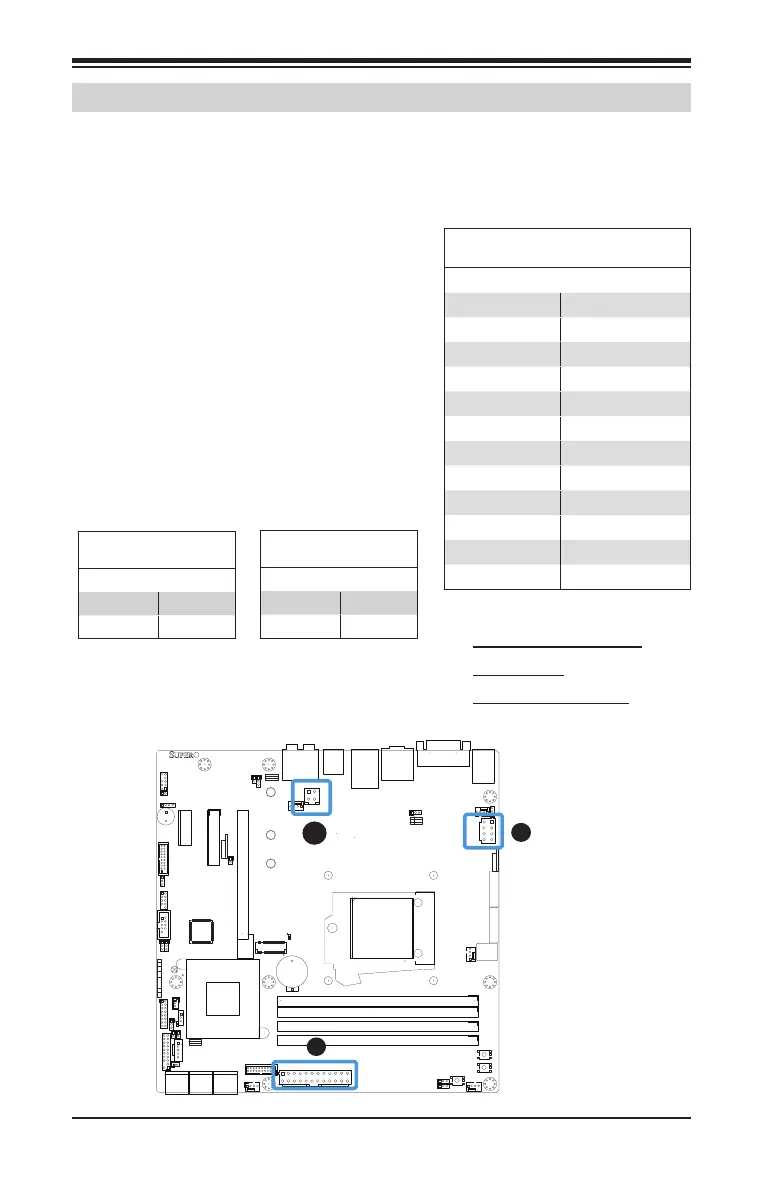
2-7 Connecting Cables
This section provides brief descriptions and pin-out denitions for on-
board headers and connectors. Be sure to use the correct cable for each
header or connector.
A. 24-Pin ATX Main PWR
B. 8-Pin PWR
C. 4-Pin Auxiliary PWR
ATX Power 24-pin Connector
Pin Denitions (JPW1)
Pin# Denition Pin # Denition
13 +3.3V 1 +3.3V
14 -12V 2 +3.3V
15 Ground 3 Ground
16 PS_ON 4 +5V
17 Ground 5 Ground
18 Ground 6 +5V
19 Ground 7 Ground
20 Res (NC) 8 PWR_OK
21 +5V 9 5VSB
22 +5V 10 +12V
23 +5V 11 +12V
24 Ground 12 +3.3V
12V 8-pin Power Connec-
tor Pin Denitions
Pins Denition
1 through 4 Ground
5 through 8 +12V
ATX Main PWR, CPU, AUX PWR
Connectors (JPW1, JPW2, JPW3)
The 24-pin main power connector (JPW1)
is used to provide power to the moth-
erboard. The 8-pin CPU PWR connector
(JPW2) is also required for the processor.
JPW3 is a 4-pin connector that provides
auxiliary power to peripheral cards and
devices. These power connectors meet
the SSI EPS 12V specication. See the
tables on the right and below for pin
denitions.
A
B
12V 4-pin Power Connec-
tor Pin Denitions
Pins Denition
1 through 2 Ground
3 through 4 +12V

 Loading...


