Chapter 2: Installation
2-19
JBR1
JTBT1
JPW3
+
MH12
JSTBY1
JF1
JTPM1
S1
JAUDIO1
JPCIE1
JPCIE2
JD1
JUSBLAN1
JBT1
FAN4
FAN1
FAN2
FAN3
FAN5
S4
S8
S11
7
JUSB30_I4
19
JPW1
1
LED1
LED2
A
C
JPW2
JHD_AC1
JI2C2
JI2C1
JL1
JSPDIF_OUT
JSMB1
JLED1
JSMB2
JPUSB2
1
JPL1
JPME2
JWD1
1
3
DESIGNED IN USA
C7Z170-M
REV:1.00
MAC CODE
BAR CODE
TP104
TP103
TP100
MH2
MH1
Power Button
BIOS Restore
CLEAR CMOS
JHD_AC1:Audio AC97 and HD audio jumper
3 PIN POWER LED
JLED1:
2-3:BIOS RECOVERY
1-2:NORMAL
JBR1:
USB 10/11(3.0)
USB 8/9(3.1)
USB 2/3
USB 4/5(3.0)
USB 6/7(3.0)
HDMI/DP
DVI
1-2 ENABLE
2-3 DISABLE
JPUSB2:USB 8/9 WAKE UP
1-2 ENABLE
2-3 DISABLE
JPUSB1:USB0/1 WAKE UP
PCH SLOT1 PCI-E 3.0 X1
JPAC1
5V STBY POWER
PCH SLOT2 PCI-E 3.0 X4
LAN
KB/MOUSE
JWD1:
JSD1:
LAN
DISABLE
ENABLE
2-3
1-2
JPL1
2-3:NMI
1-2:RST
WATCH DOG
CPU
2-3:ME MANUFACTURING MODE
/CPU FAN
USB 0/1
1-2:NORMAL
JPME2:
SATA DOM PWR
JTPM1:TPM/PORT80
JL1:
AUDIO FP
HDD PWR
LEDLED
CMOS CLEAR
DIMMB1
DIMMB2
NIC1
SPEAKER:1-4
JD1:
BUZZER:3-4
JI2C1/JI2C2
ON:ENABLE
OFF:DISABLE
NIC2
HD AUDIO
OH/FF
LED
CHASSIS INTRUSION
DIMMA1
DIMMA2
RST
PWR
JF1
ON
ALWAYS POPULATE RED SOCKET FIRST
UNB NON-ECC DDR4 DIMM REQUIRED
CPU SLOT3 PCI-E 3.0 X16
M.2 PCI-E X4
COM1
2-3:DISABLE
1-2:ENABLE
JPAC1:AUDIO
I-SATA2
I-SATA3
I-SATA1
I-SATA5
I-SATA0
I-SATA4
BT1
S/PDIF OUT
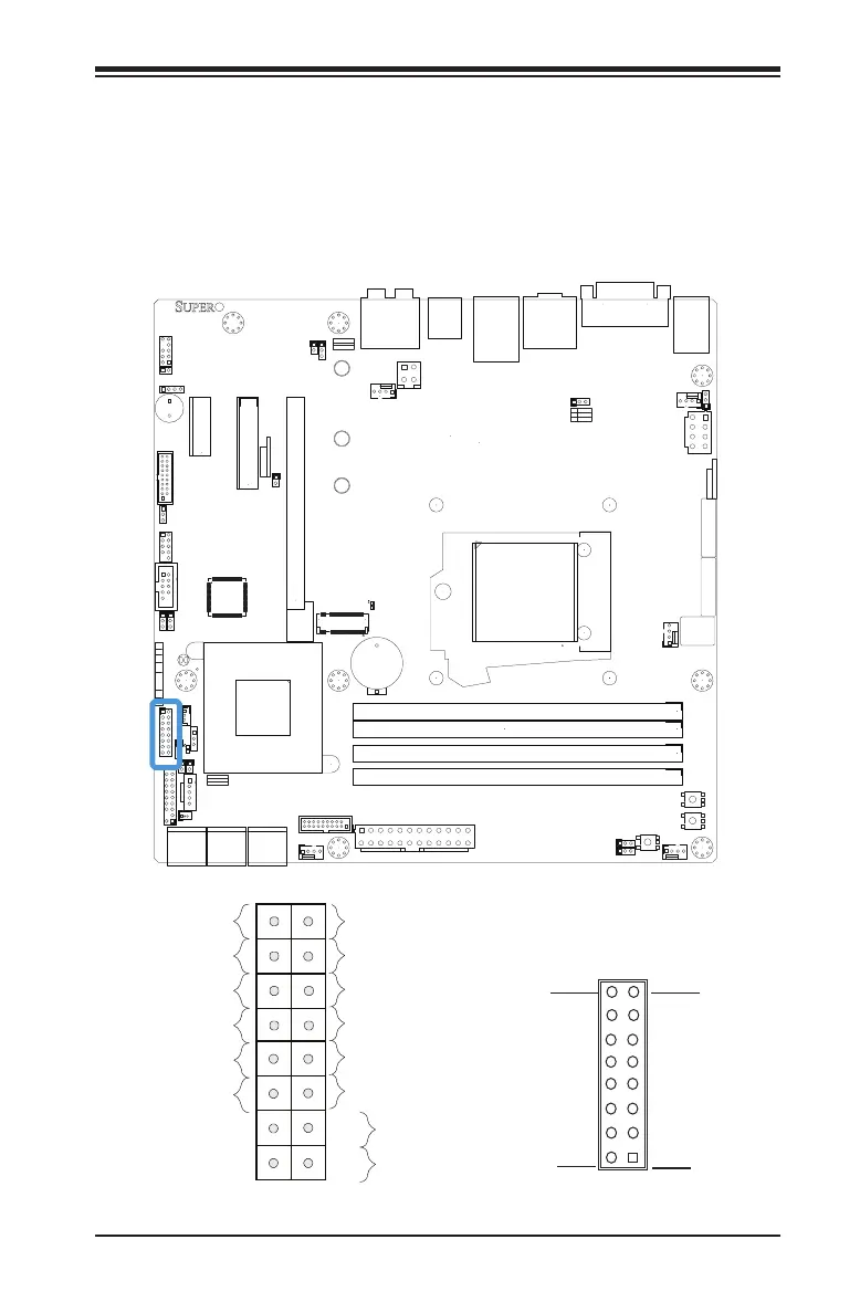
Front Control Panel
JF1 contains header pins for various buttons and indicators that are
normally located on a control panel at the front of the chassis. These
connectors are designed specically for use with Supermicro chassis. See
the gure below for the descriptions of the front control panel buttons
and LED indicators. Refer to the following section for descriptions and
pin denitions.
Pin 15Pin 16
Pin 1
Pin 2
JF1 Header Pins
Power Button
LED
1
NIC1 LED
Reset Button
2
HDD LED
Power LED
Reset
PWR
Vcc
Ground
Ground
X
X
Vcc
Vcc
Vcc
X
X

 Loading...


