Chapter 2: Installation
2-17
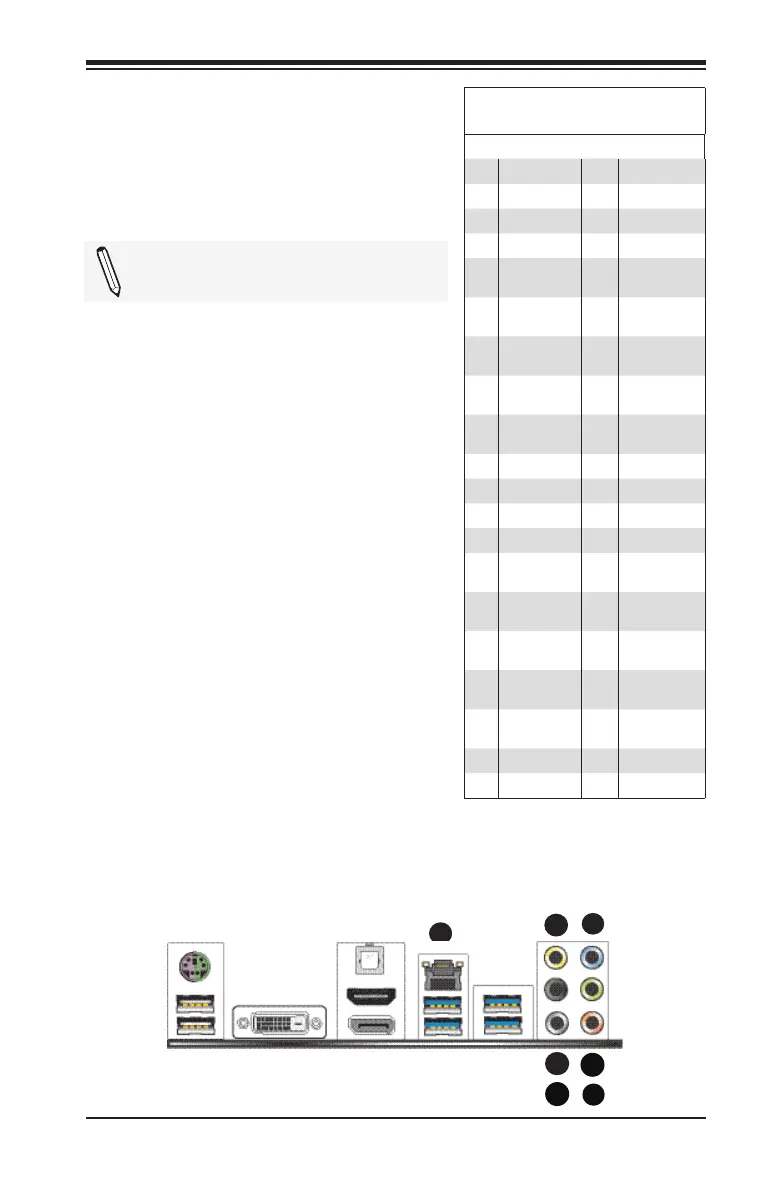
Ethernet Port
One Gigabit Ethernet port (LAN) is lo-
cated next to the S/PDIF port on the
I/O Backpanel to provide network con-
nections. This port will accept RJ45 type
cables.
Note: Please refer to the LED Indica-
tor Section for LAN LED information.
LAN Port
Pin Definition
Pin Description Pin Description
1 VBUS1 21 TX1-
2 D1N 22 TX2+
3 D1P 23 TX2-
4 GND 24 TX3+
5 STDA_SS-
RX1N
25 TX3-
6 STDA_SS-
RX1P
26 TD4+
7 GND_
DRAIN
27 TX4-
8 STDA_
SSTX1N
28 GND
9 STDA_
SSTX1P
29 ORG-/GRN+
10 VBUS2 30 ORG+/GRN-
11 D2N 31 YEL+
12 D2P 32 YEL-
13 GND 33 CG1
14 STDA_SS-
RX2N
34 CG2
15 STDA_SS-
RX2P
35 CG3
16 GND_
DRAIN
36 CG4
17 STDA_
SSTX2N
37 CG5
18 STDA_
SSTX2P
38 CG6
19 Vcc 39 CG7
20 TX1+ 40 CG8
A. LAN1
B. Center/LFE Out
C. Surround Out
D. S-Surround
E. Line In
F. Line Out
G. Mic In
Back Panel High Denition Audio
(HD Audio)
This motherboard features a 7.1+2
Channel High Denition Audio (HDA) co-
dec that provides 10 DAC channels. The
HD Audio connections simultaneously
supports multiple-streaming 7.1 sound
playback with 2 channels of independent
stereo output through the front panel
stereo out for front, rear, center and
subwoofer speakers. Use the Advanced
software included in the CD-ROM with
your motherboard to enable this func-
tion.
A
E
B
G
C
D

 Loading...


