Chapter 2: Installation
2-25
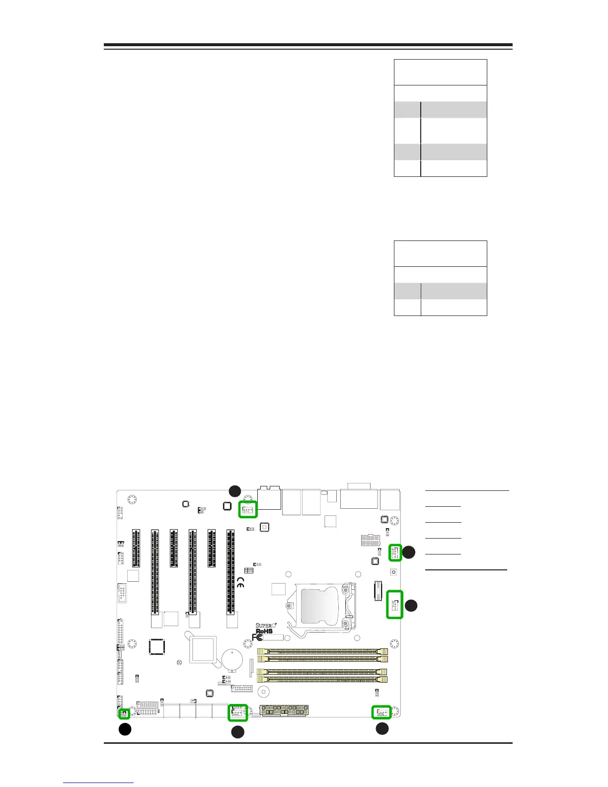
Fan Header
Pin Denitions
Pin# Denition
1 Ground (Black)
2 2.5A/+12V
(Red)
3 Tachometer
4 PWM_Control
Fan Headers (Fan 1 ~ Fan 5)
The X10SAT has ve fan headers (Fan 1~Fan
5). These fans are 4-pin fan headers. Although
pins 1-3 of the fan headers are backward com-
patible with the traditional 3-pin fans, we recom-
mend the use 4-pin fans to take advantage of
the fan speed control via IPMI interface. This
allows the fan speeds to be automatically ad-
justed based on the motherboard temperature.
Refer to the table on the right for pin denitions.
A
B
A. Fan 1 (CPU Fan)
B. Fan 2
C. Fan 3
D. Fan 4
E. Fan 5
F. Chassis Intrusion
C
D
E
Chassis Intrusion (JL1)
A Chassis Intrusion header is located at JL1 on
the motherboard. Attach the appropriate cable
from the chassis to inform you of a chassis intru-
sion when the chassis is opened.
Chassis Intrusion
Pin Denitions (JL1)
Pin# Denition
1 Intrusion Input
2 Ground