Chapter 1: Introduction
1-5
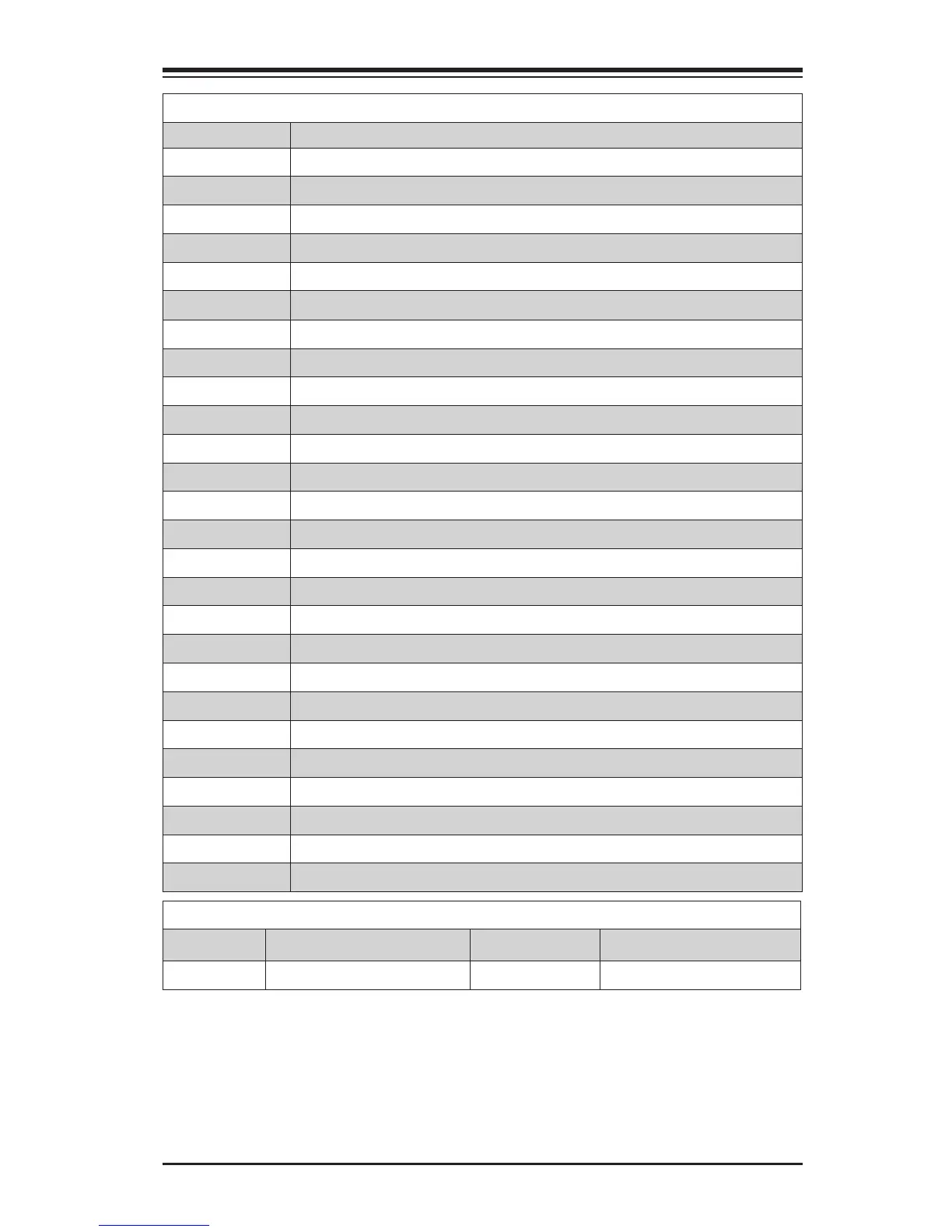
Connectors and Switches
Connector Description
I/O Back Panel See page 2-16 for details
Audio FP Front Panel Audio Header
Battery Onboard Battery
COM1 COM1 Port Header
Fan 1,2,3,4,5 System/CPU Fan Headers (Fan1: CPU Fan)
JD1 Speaker/buzzer (Pins 1-2: Buzzer, Pins 1~4: External Speaker)
JF1 Front Panel Control Header
JL1 Chassis Intrusion Header
JL2 Reserved
JLED1 Power LED Indicator Header
JPW1 24-pin ATX Main Power Connector (Required)
JPW2 +12V 4-pin CPU power Connector (Required)
JSD1 SATA DOM (Disk On Module) Power Connector
JSPDIF_OUT Sony/Philips Digital Interface (S/PDIF) Out Header
JSTBY1 Standby Power Header
JTPM1 Trusted Platform Module/Port 80 Connector
SP1 Internal Speaker/Buzzer
A-SATA0/1 (ASMedia) Serial ATA (SATA 3.0) Port 0 / Port 1(6Gb/sec)
I-SATA0~5 (Intel C226) Serial ATA (SATA 3.0) Ports 0~5 (6Gb/sec)
USB 0/1 Front Panel Accessible USB 3.0 Ports 0/1 (USB 2.0 12/13)
USB 2/3 Front Panel Accessible USB 3.0 Ports 2/3 (USB 2.0 2/3)
USB 4/5, 6/7 Front Panel Accessible USB 2.0 Headers 4/5,6/7
POWERBUTTON Internal Power Button
CLEAR CMOS Resets the contents of the CMOS to default values
J_1394 1394 (Firewire®) Header
T-SGPIO1 / 2 Serial Link General Purpose Header
LED Indicators
LED Description Color/State Status
LED1 Onboard Standby PWR LED Green: Solid on Power On