© Copyright Mission Critical Energy Inc, 2019 Version 1-2019
www.superwind.com
AWG Wire Size Chart for Superwind 350/48V
Table No. 6.3.1
Distance from mast top to the battery
Minimum gauge
(cross section)
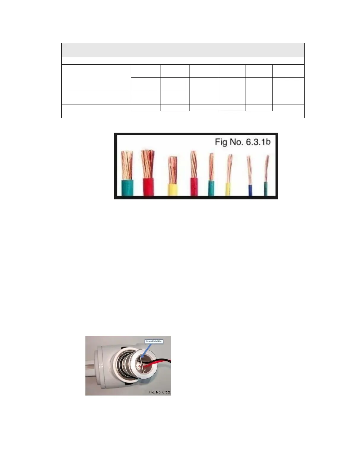
The use of multi-strand, marine grade wire is recommended.
Solid wire is not recommended!
Tinned multi-strand, marine grade wiring is recommended for all marine insulations to
reduce corrosion issues.
For underground installations, the cable must be installed in conduit or be suitable for
direct bury applications. All cables and materials (heat shrink, insulating tape, etc)
should be ultraviolet resistant.
Chafe protection should be provided for the entire cable run. All penetrations into the
mast, electronics enclosures, etc, should be de-burred and the cable protected against
chafe using rubber sleeves, grommets, etc.
All wire terminations and connections must be made using suitable (preferably marine
grade) crimp on connectors.
6.3.2 Strain Relief
Depending on mast length and cable cross section,
the weight of the cable inside the mast can be
considerable. If the cable weighs more than 5 kg
(11 lbs) strain relief must be provided inside the
mast to prevent damage to the internal connection
point of your Superwind 350/48V (Fig. No. 6.3.2)