© Copyright Mission Critical Energy Inc, 2019 Version 1-2019
www.superwind.com
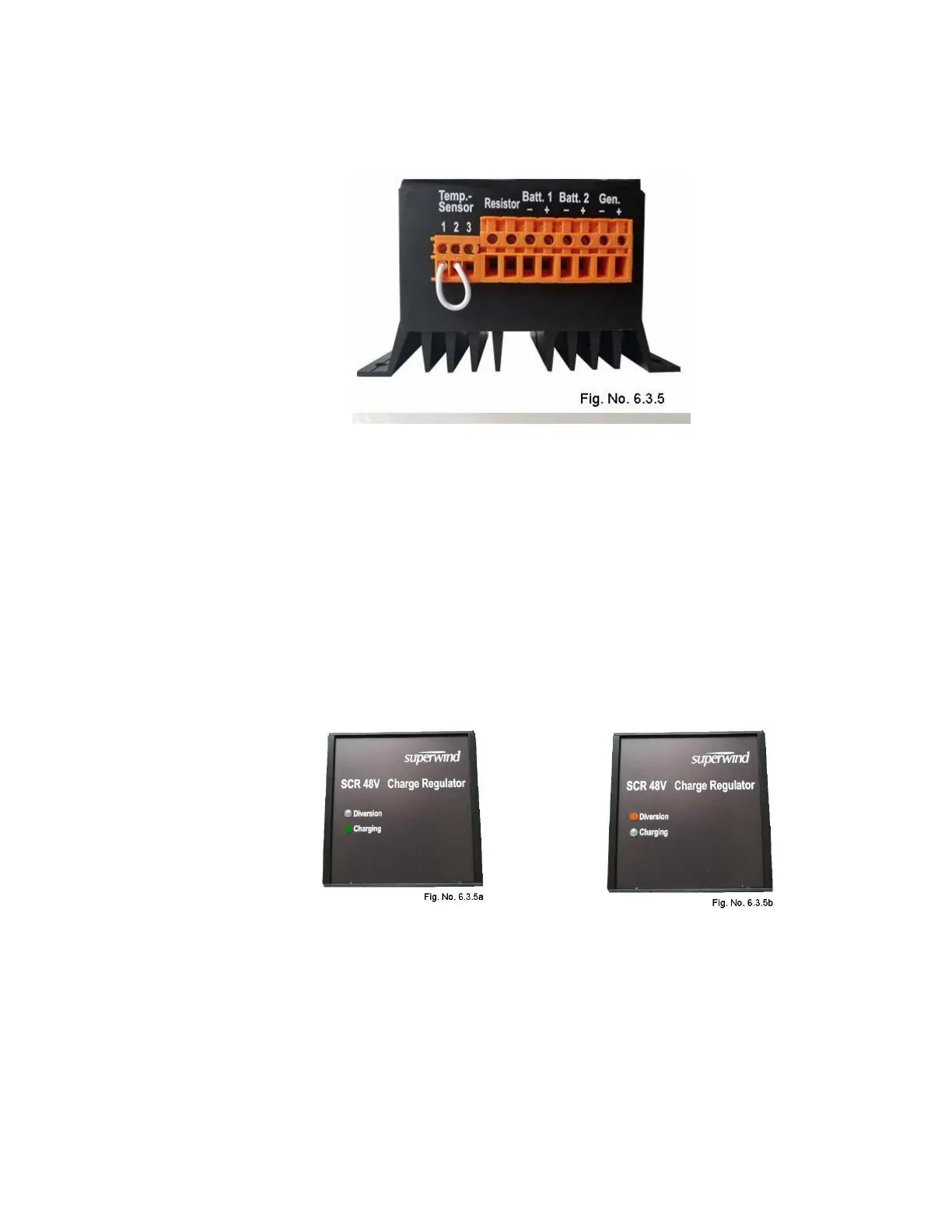
6.3.5 Charge regulator SCR 48 V
6.3.5.1 Technical data
Nominal voltage ............................................................................. 48 V
Max. Charging voltage (25°C)........................................................ 57.6 V
Temperature compensation ........................................................... 144 mV/°C
Max. Current .................................................................................. 10 A
Resistance of dump resistor .......................................................... 5.6 Ohm
Number of charging outputs ........................................................... 2
Method of voltage regulation .......................................................... PWM
Connecting terminals ..................................................................... 4mm²
AWG12
The illuminated GREEN “Charging” LED as shown in Fig No. 6.3.5a indicates
charge current is being sent to the battery.
The illuminated ORANGE “Diversion” LED as shown in Fig No. 6.3.5b
indicates the PWM circuit is limiting the charge voltage sent to the battery by
diverting excess power to the power resistor.
The default diversion set point level for the maximum charging voltage can be
adjusted as required to meet customer requirements. As special equipment is
required for proper calibration, this adjustment can only be performed by the
manufacturer or a Superwind authorized service partner.