© Copyright Mission Critical Energy Inc, 2019 Version 1-2019
www.superwind.com
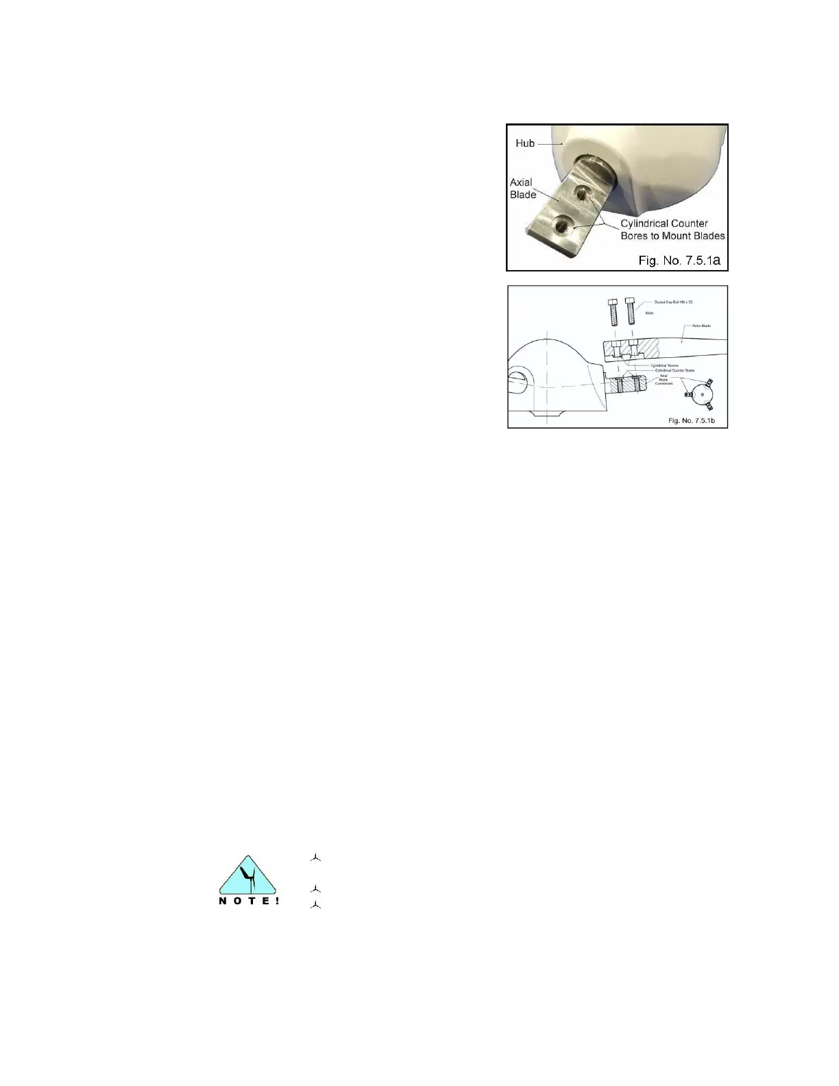
7.5.1 Attaching the rotor blades to the hub
Accurate positioning and mounting of the rotor
blades to the hub is ensured by their design,
which allows for one way installation only. The
flat portions of the axles sticking out (Fig. No.
7.5.1a) of the hub have two cylindrical counter
bores each. The rotor blades have rectangular
recesses with two cylindrical Tenon’s, which fit
into the cylindrical counter bores of the axle
when pressed with light force.
The rotor blades are attached by two M6 x 25
socket cap screws, the threads of which are
coated with TUFLOK to prevent loosening
during operation (Fig. No. 7.5.1.b). Due to this
coating, some resistance during installation is
normal.
To begin assembly of the rotor:
1. Place the hub with the flat side down on a soft surface with the three flat axles
horizontal and pointing upwards.
2. Attach the first rotor blade by aligning the cylindrical tenons of the blade to the
cylindrical counter bores of the axel and lightly pressing the blade into place. Use
caution, as the use of too much force can damage the threads.
3. Once both tenons are aligned correctly with the counter bores, screw in the two
socket cap screws M6 x 25 (Fig. No. 7.5.1b). Stainless steel threads are very soft,
so make sure the screws are first started by hand and not cross threaded. If
mounting the blade for the first time, it is recommended to insert the screws and
alternatively give each a half turn until the tenons are completely pressed into the
counter bores.
4. When the rotor blade is attached to the axle, do not simply tighten the screws, as
excessive force could damage the blade material. For the correct initial tension,
use a torque wrench to tighten the screws to a torque of 4.5 Nm. [3.31 lb/ft].
If a torque wrench is not available, the following method is recommended:
1. To ensure the contact surface on each blade face and adjoining axle fits properly,
insert both screws slowly, with offset pressure - one after the other - until snug.
Once properly positioned, increase the pressure slightly on each screw until it
starts to feel tight.
2. At this point, turn the screw exactly one quarter turn in order to adjust to the
correct final tension.
3. Continue mounting the other two blades the same way.
Ensure that the cylindrical tenons on each of the blades are
correctly inserted into the axle counter bores.
Do not use excessive force when installing the blades.
Do not over tighten the screws.