© Copyright Mission Critical Energy Inc, 2019 Version 1-2019
www.superwind.com
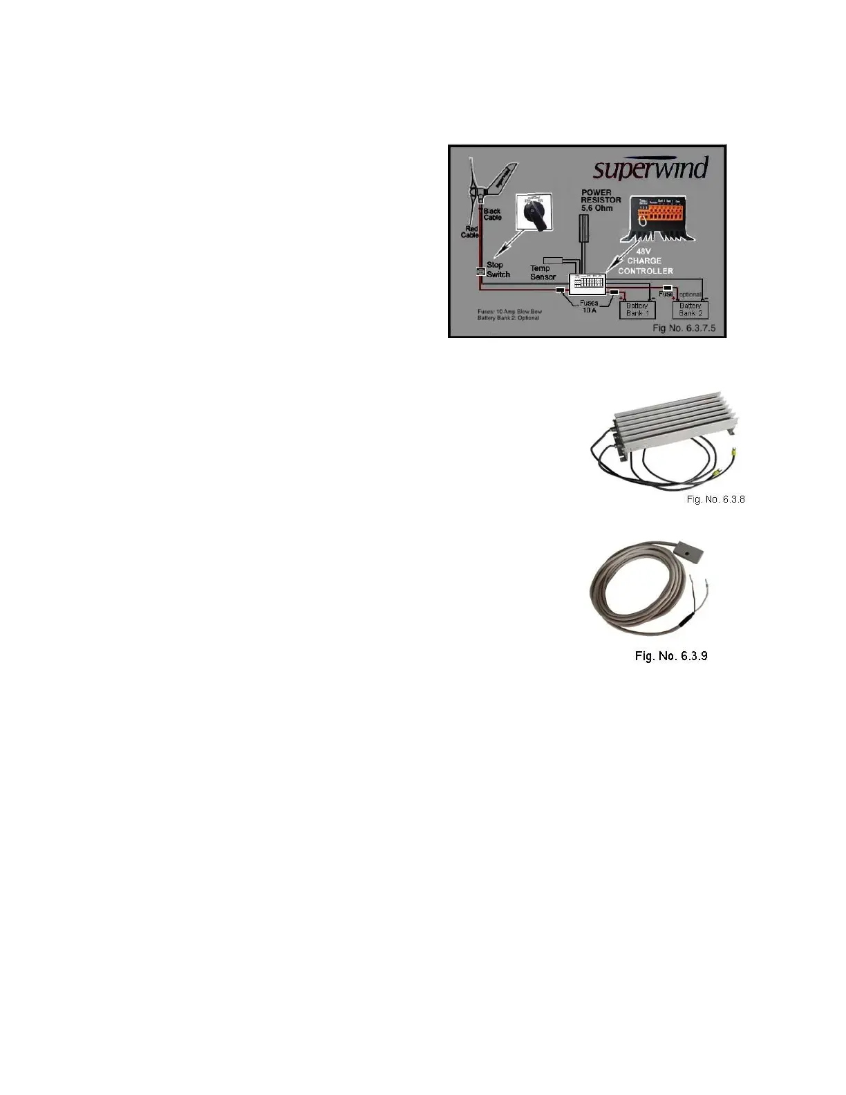
6.3.7.5 Component locations
The SCR 48V Charge
Controller is installed
between the battery bank and
the wind turbine. The Stop
Switch is installed between
the Superwind 350/48V and
the charge controller. The
required 10 Amp slow-blow
fuses are installed before and
after the SCR 48V Charge
Controller as shown in Fig.
No. 6.3.7.5
6.3.8 Diversion Load Power Resistor
The resistance of the wires connecting the power resistor to
the charge regulator can affect the charging voltage. As
such, the length of the wires connecting the power resistor
should not exceed the provided 1 meter (3 feet). If it is
necessary to extend the resistor wires run beyond 1 meter,
please refer to the AWG Wire Size Chart (Table No. 6.3.1
and Figs. 6.3.1a and 6.3.1b).
6.3.9 Temperature Sensor
The remote temperature sensor is a 6.4 meter (25’) long
cabled sensor designed to provide battery temperature
compensation charging from the SCR 48V charge regulator.
The sensor cable wires are non-polarity specific, meaning
the two plug connections at the charge regulator are
interchangeable.
6.4 Grounding
Your Superwind should be properly grounded to protect the system against damage
due to lightning, over voltage, etc. Grounding system design depends on factors such
as local conditions, place of installation, type of soil, depth of groundwater table or the
availability of a pre-existing grounding bus. Consult a competent electrician or
electrical system technician should questions exist concerning the design or
installation of the grounding system.