© Copyright Mission Critical Energy Inc, 2019 Version 1-2019
www.superwind.com
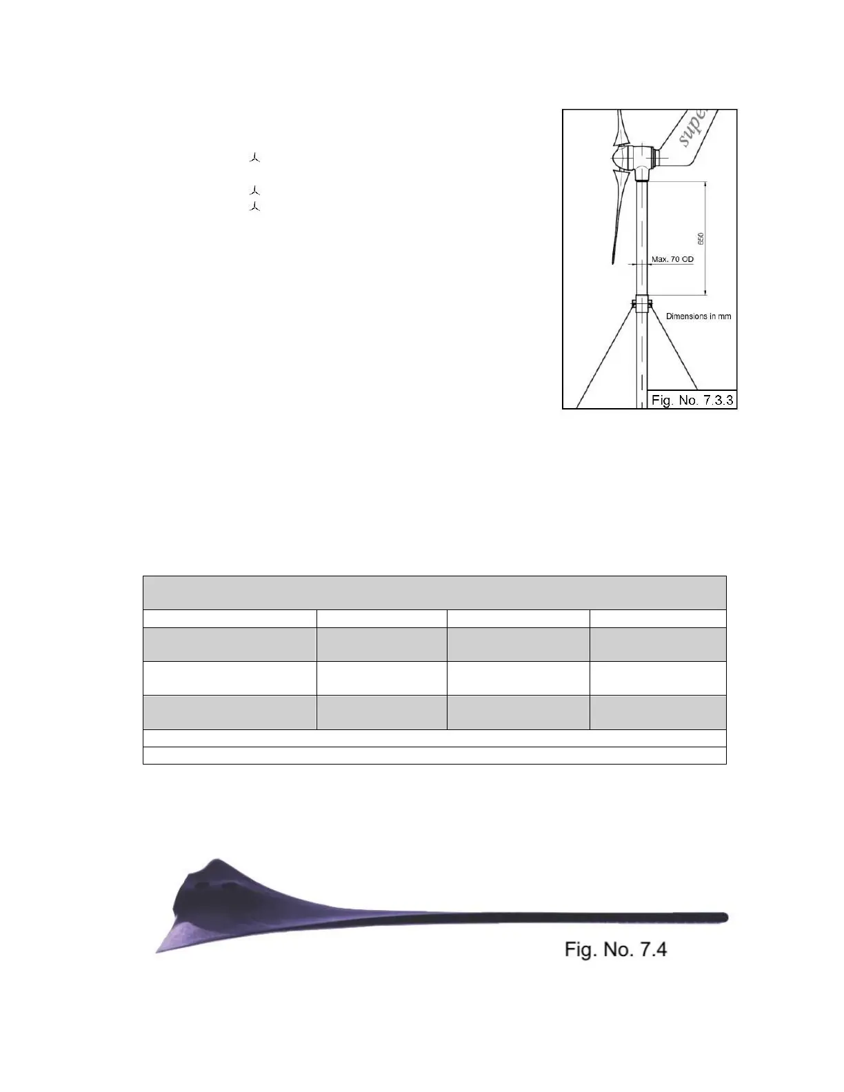
7.3.3.1 Preparations at the mast head:
Deburr the end of the tube carefully (inside
and outside).
File off the welding seam if necessary.
Drill two holes at 7 mm.
Depending on the size of the tube, it is possible
that the two hexagon socket button head
screws provided for attachment (M6 x 12) may
be too short. Should this be the case, screws of
the appropriate length must be used. Ensure
that the replacement screws are of sufficient
length for the installation, but are not long
enough to touch the inner part of the yaw shaft.
Otherwise the sound and vibration dampening
ability of the installation will be compromised.
Apply a small amount of Locktite® to the
threads of the bolts prior to installation.
7.3.4 Mast Tube Specifications
The proper sizing for a mast selection is 2” schedule 40 stainless steel or aluminum
piping. Stainless steel tubing can be used as well, provided the size is 2 ¼”, 316L, 16
Gauge. However, any type of high quality, commercial grade metal can be used,
provided it is 2” schedule 40.
Common American Masts
Chart No. 7.3.4
Stainless Steel Pipe
(2” sch 40)
Stainless Steel Tube
(2 ¼”, 316L, 16 Gauge)
Aluminum Pipe
(2” sch 40)
*Inches are rounded to nearest thousandth
**Inches are rounded to nearest hundredth
7.4 Rotor Blades