Do you have a question about the SUPMEA SUP-LDG and is the answer not in the manual?
Content of the document, copyright, data protection, and manufacturer's rights.
Guidelines for personnel authorized to install, use, operate, and maintain equipment.
Checks for package damage, packing list verification, and nameplate confirmation.
Explanation of Faraday's law of electromagnetic induction and induced electromotive force equation.
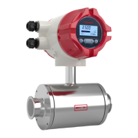
Components of the electromagnetic flowmeter: converter, flange, lining, electrode, measuring tube, coil, casing.
Use for conductive liquids or liquid-solid two-phase flow, conductivity requirements, and application scope.
Wiring diagrams and terminal descriptions for remote and compact type flowmeters.
Checking nameplate details for order consistency and correct ex-factory parameters.
Tips for checking boxes, packing lists, and instrument nameplates for order conformity.
Guidelines for storing the instrument in a dry, clean place, away from direct sunlight.
Considerations for pipe design, including space and vibration to avoid.
Location requirements: dry, ventilated, avoid water accumulation; avoid direct sun/rain, temperature variation.
Flow direction, horizontal/vertical installation, liquid-filled pipes, avoiding pump suction, control valve placement.
Ensuring coaxiality, cleaning pipelines, correct lifting, avoiding vibration, protecting flange, terminal box sealing.
Pipeline calibration, coaxiality checks, and cleaning foreign matter before installation.
Care during unpacking, avoiding vibration, protecting flange surface, and terminal box sealing.
Ensuring correct flow direction, washer installation, welding precautions, terminal box sealing, and flange connection.
Table and diagrams showing dimensions for various DN sizes and flange specifications.
Safety precautions before electrical work, observing regulations, and trained personnel.
Danger warnings for connecting cables with power off, grounding importance, and explosion-proof notes.
Importance of grounding the sensor and converter separately to prevent interference and ensure functionality.
Grounding equipment for operator safety, and details for 100-240VAC and 24VDC power supplies.
Details on current output (4-20mA), communication output (RS485), and pulse/frequency/relay outputs.
Pre-power on checks: installation compliance, power supply connection, electrical connection, and cover tightening.
Instrument configuration at delivery, self-check upon energization, and initial display.
Description of display indicators, information types, and operation keys (mechanical/photoelectric).
Instructions for photoelectric key operation, including click duration and finger placement.
Instructions for handling mechanical keys and entering configuration mode.
Accessing parameter setting interface and entering the password for quick setup.
Parameters for flow, units, density, time constant, flow resection, direction, mode, and spike suppression.
General operating instructions, parameter selection, and adjustment methods.
Entering parameter setting, password input, and adjusting parameter values using buttons.
Displaying measurement values after startup, including flow, cummulant, and conductivity.
Flow setup, units, density, correction, and analog output parameter configuration flowcharts.
Configuration for pulse output type, transistor state, max frequency, and accumulation settings.
Setup menus for system, empty pipe, sensor parameters, and test functions.
Flowmeter self-diagnosis function, providing alarm messages for power supply or hardware failures.
Usage of pulse, frequency, and current outputs for calibration and data transmission.
Using pulse equivalent for calibration, user measurement, and volume indication.
Frequency output for calibration and measurement, corresponding to real-time and max flow rates.
Current output (4-20mA) for transmitting data to other instruments like recorders or PLCs.
RS485 communication interface with MODBUS-RTU protocol for data reading.
Table of parameters, data types, register addresses, and explanations for communication.
Settings for mailing address, baud rate, parity, and data arrangement in communication frames.
Examples of sending and returning messages for reading real-time flow and accumulated values.
Detailed specifications for measuring system, communications, display, accuracy, and operating environment.
Corrosion resistance of electrode materials (e.g., Stainless Steel, Hastelloy, Ti) for various media.
Nominal diameter and corresponding flow ranges (m³/h) for the flowmeter.
Table correlating flow velocity (m/s) with flow rate (m³/h) for different DN sizes.
Accuracy specifications under reference conditions: medium, temperature, pressure, and conduit lengths.
Characteristics of plug-in sensors: no moving parts, easy installation, accuracy, low pressure loss, cost-effective.
Product type is magnetic insertion; structure types: measurement tube and plane electrode.
Specifications: pipe diameter, flow range, accuracy, conductivity, pressure, electrode material, temperature, protection level.
Components of the sensor: measuring head, excitation system, insertion rod, junction box, mounting base, sealing mechanism.
| Brand | SUPMEA |
|---|---|
| Model | SUP-LDG |
| Category | Measuring Instruments |
| Language | English |