C010
C140
C060
C150
C020
C090
Bostik
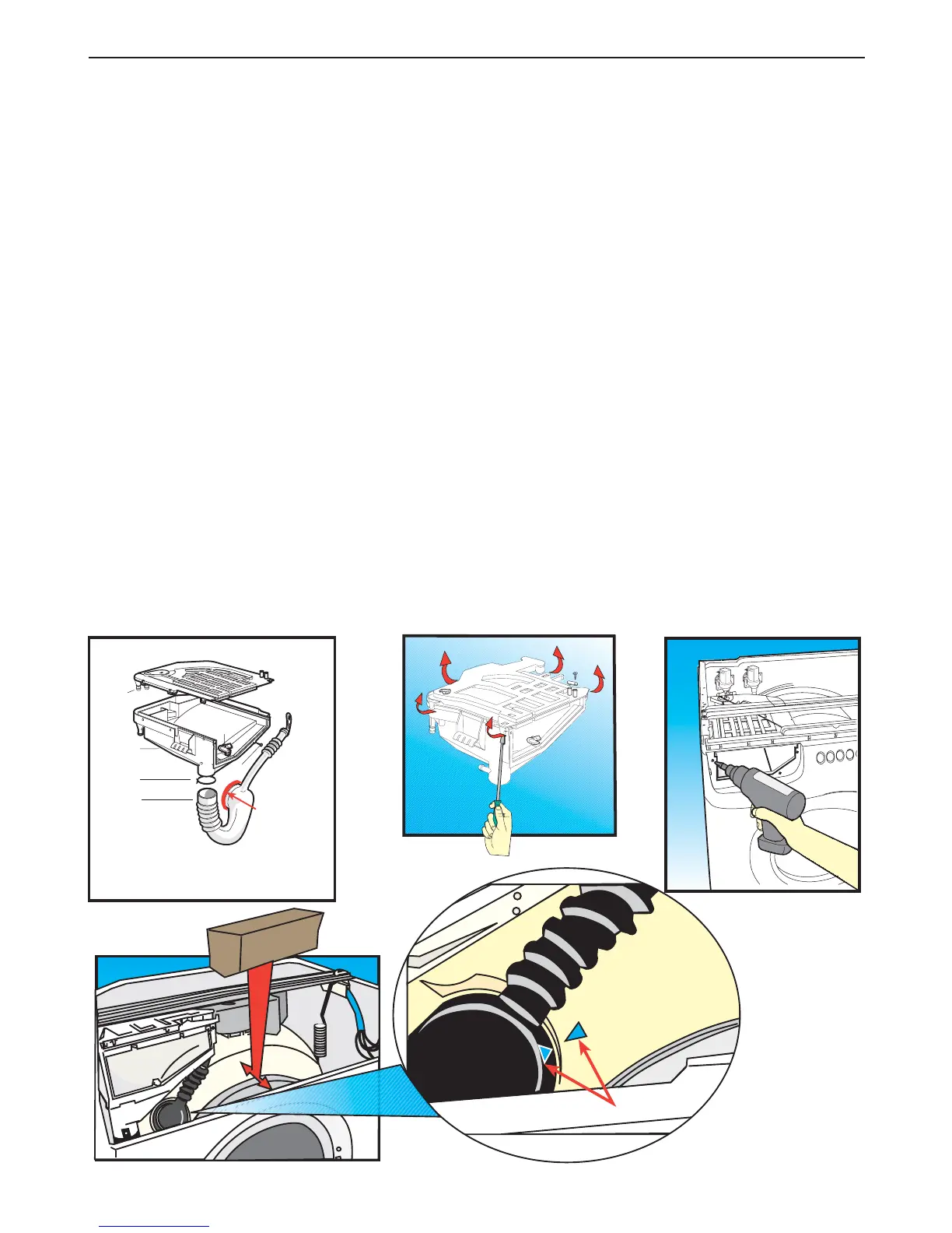
Step 12 For 39 cm washing machines:
Removing:
- the detergent dispenser cover (C020)
- the detergent dispenser (C010)
- the detergent feed/steam discharge coupling (C060).
Common operations:
(a) Remove the top cover (Step 1).
(b) Remove the rear cover (Step 2).
(c) Remove the detergent drawer (C030) from its housing by levering downwards and pulling. (Step 21).
(d) Remove the three steel screws (C150) securing the dispenser to the front panel.
(e) Use a long crosshead screwdriver to remove the four fixing screws securing the control panel
(Step 28), without disconnecting the components.
(f) Release the steam discharge coupling fitted on the right of the dispenser.
(g) Remove the hose clips (C130) from the solenoid valve pipes and disconnect them from the detergent
dispenser together with the air-break-filter hose (D370).
(h) Use a pair of pliers to remove the spring clip (C140) securing the detergent feed coupling to the
dispenser.
- the detergent dispenser cover (C020) and/or the detergent dispenser (C010)
(i) From the top, remove the detergent dispenser from its housing.
(j) Use a flat screwdriver to lever the sides of the cover (C020) near to the lugs clamping it to the
dispenser body (C010) and lift off the cover.
If necessary, at this point replace the detergent dispenser (C010).
To re-assemble, follow the same procedure in reverse order making sure that all the parts not involved
in the operation are recovered.
- the detergent feed/steam discharge coupling (C060)
(k) Remove the detergent feed and steam discharge coupling (C060) from the tub.
(l) To re-assemble:
Insert a spacer between the tub and the front panel of the cabinet (see figure) in order to obtain more
working space for fitting the detergent feed coupling. Apply a Bostik type sealant between the coupling
and the tub, fit the new coupling making sure that the reference marks on the tub and coupling are
aligned (see figure).
Continue following the same procedure in reverse order.
Position spring clip (C140) in such a manner that it does not interfere with the tub during operation.
Screws (C150) securing the detergent dispenser to the front panel must be screwed in using a
manual screwdriver to prevent stripping the threads in the detergent dispenser holes.
D
A
S
V
D
FFB
V
V, LB
B
2