N.B.
N.B.
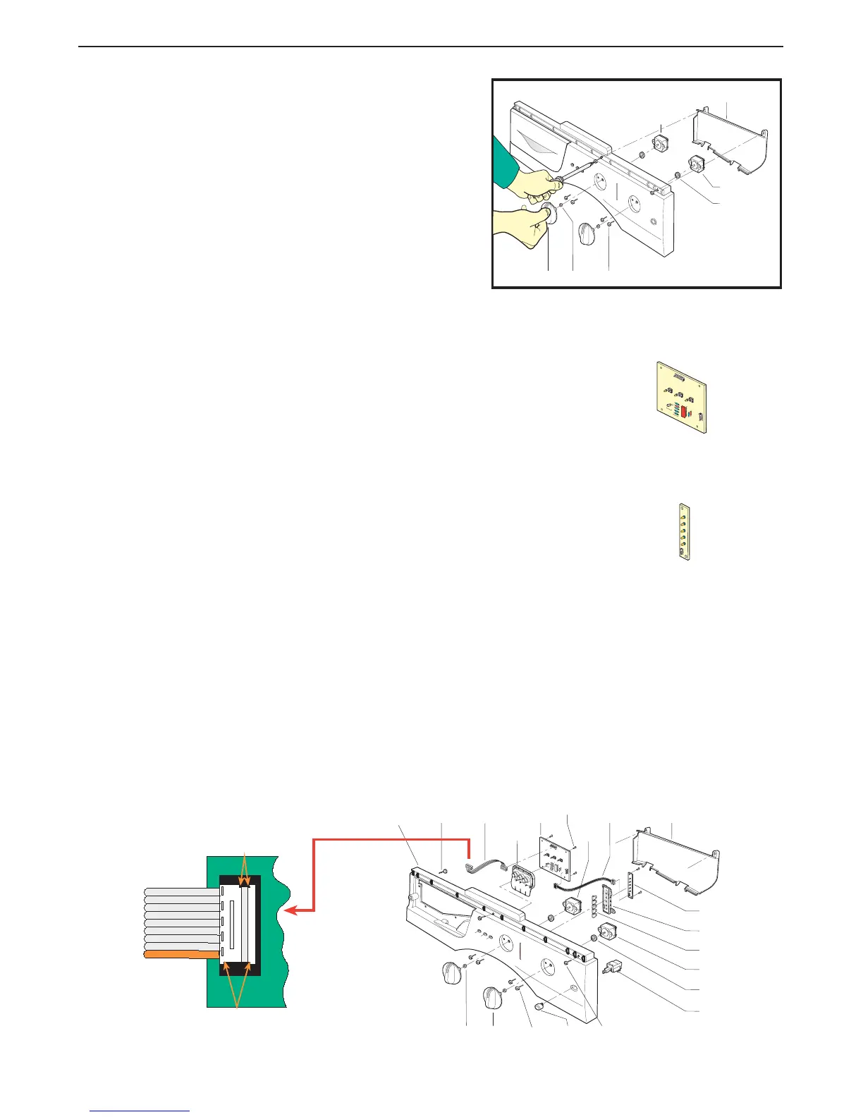
Step 27 Removing the front panel buttons with gasket (B062):
(a) Remove the top cover (Step 1).
(b) Remove the electric component cover plate (B032) (Step 24).
(c) Use a short crosshead screwdriver to unscrew the six fixing screws (B029) securing the printed
circuit board (B028).
(d) Disconnect the ribbon cable (B057) to obtain more working space.
(e) Remove the control panel button gasket (B062).
(f) To re-assemble, follow the same procedure in reverse order, making sure that the ribbon cables
are connected in the right positions.
Step 24 Removing and/or replacing:
- the knob (B059)
- the electric component cover plate (B032)
- the potentiometer (B003) or programme selector (B022)
(a) Remove the top cover (Step 1).
(b) Grasp the knob (B059) tightly and remove it.
(c) Use a crosshead screwdriver to unscrew the two
fixing screws (B033) securing the electric component
cover plate (B032) and remove the plate
(where fitted).
(d) Unscrew the two fixing screws (B002) securing the
program selector (B003), disconnect the wiring and
replace the program selector (B022) or potentio-
meter (B003), taking care to recover the washer
(B036).
(e) To re-assemble, follow the same procedure in reverse
order.
Step 26 Removing the led circuit board (B034):
(a) Remove the top cover (Step 1).
(b) Remove the electric component cover plate (B032) (Step 24).
(c) Use a short crosshead screwdriver to unscrew the six fixing screws (B029)
securing the printed circuit board (B034).
(d) Disconnect ribbon cable (B057)
(e) To re-assemble, follow the same procedure in reverse order, making sure
that the ribbon cables are connected in the right positions. Check that the
indicator lights are correctly inserted in their housings (B031) to prevent possible malfunction.
CONTROL PANEL
Step 25 Removing and/or dismantling the led printed circuit board (B028):
(a) Remove the top cover (Step 1).
(b) Remove the electric component cover plate (B032) (Step 24).
(c) Use a short crosshead screwdriver to unscrew the four fixing screws (B029)
securing the printed circuit board (B028).
(d) Disconnect the ribbon cable (B057).
(e) To re-assemble, follow the same procedure in reverse order, making sure that the
ribbon cable is connected in the right position.
B032
B023
B033
B040
B022
B036
B074
B031
B034
B010
B290 B058
B029
B028
B003
B062
B057
B210 B059 B002
B003
B059 B002B210
B032
B022
B036
 Loading...