4-12 FUEL AND LUBRICATION SYSTEM
REASSEMBLY
Reassemble the carburetor in the reverse order of disassembly.
Pay special attention to the following points:
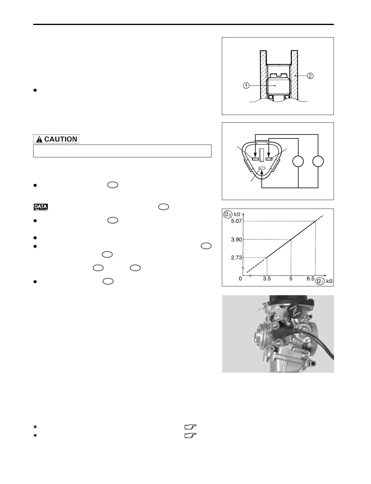
PILOT SCREW
After cleaning, install the pilot screw 1 to the original setting
by turning the screw in until it lightly seats, and then backing it
out the same number of turns counted during disassembly.
1 Pilot screw
2 Carburetor body
Replace the removed O-ring with a new one.
THROTTLE POSITION SENSOR INSTALLATION
Install the throttle position sensor as described below.
Measure the resistance
Ω1
between the throttle position sen-
sor terminals as shown in the illustration.
Throttle position sensor resistance
Ω1
: 3.5 – 6.5 k
ΩΩ
ΩΩ
Ω
Measure the resistance
Ω2
between the throttle position sen-
sor terminals as shown in the illustration.
Fully open the throttle valve with the throttle lever.
Adjust the throttle position sensor’s angle until resistance
is 78 % of resistance
Ω1
.
For example: When
Ω1
is 5 k
ΩΩ
ΩΩ
Ω,
Ω2
should be 3.9 k
ΩΩ
ΩΩ
Ω.
When the resistance
Ω2
is within specification, tighten the
throttle position sensor mounting screws.
Ω
1
Ω
2
Bl
Y
B
REMOUNTING
Remount the carburetor assembly in the reverse order of re-
moval. After the carburetor assembly has been remounted onto
the engine perform the following adjustments:
Throttle cable play ................................................ 2-13
Engine idle speed ................................................. 2-14