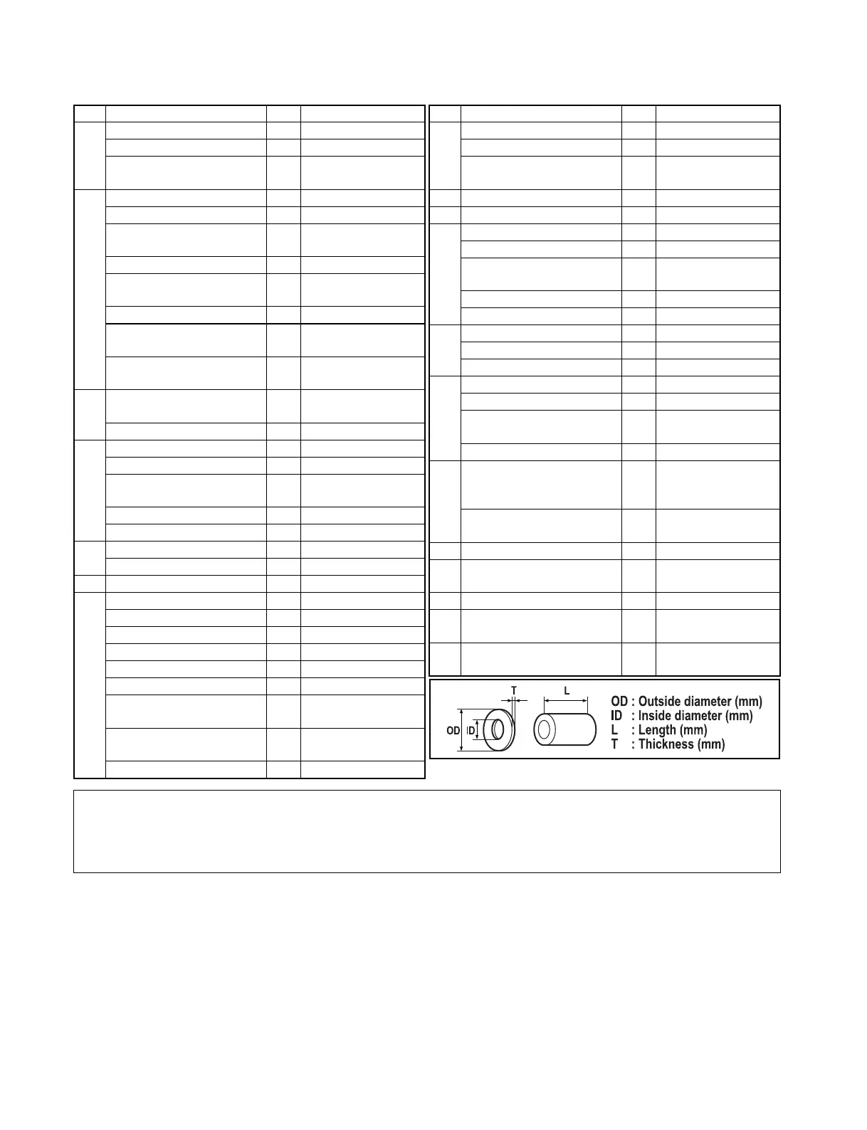
4
LOCATION OF PARTS
Check all the components which have been removed from the base of the crate.
Item Part Name Q’ty Remarks
A
Headlight cover 1
Screw 3 6 × 12 mm
Stepped washer 3
OD:16.0 ID:6.5
T:4.5
B
Handlebars assembly 1
Clamp 2
Bolt (with lock washer) 4
8 × 35 mm
“7” marked bolt
Throttle cable clip 1
Rubber boot 1
For clutch lever
adjuster
Strap 2 L:120
Screw 1
5 × 20 mm For
throttle assembly
Screw 2
5 × 45 mm
For left switch
C
Holder 1
For front brake
master cylinder
Flange bolt 2 6 × 22 mm
D
Handlebar balancer weight 2 Right and Left
Screw 2 6 × 55 mm
Washer 2
OD:16.0 ID:6.5
T:4.0
Rubber cushion 2
Spacer nut 2 6 mm
E
Front turn signal light 2 Right and Left
Flange nut 2 10 mm
F Rear view mirror 2 Right and Left
G
Knuckle cover 2 Right and Left
Screw 1 5 × 10 mm
Washer 1 OD:16.0 ID:5.5
Washer 1 OD:16.0 ID:6.5
Crown nut 1 6 mm
Washer (Black) 1 OD:20.0 ID:6.5
Washer (Black) 1
OD:16.5 ID:6.5
T:1.6
Stepped washer (Black) 1
OD:16.0 ID:6.5
T:5.5
Self-lock nut 2 6 mm
Item Part Name Q’ty Remarks
H
Front fender 1
Flange bolt (with washer) 4 6 × 16 mm
Collared spacer 4
OD:17.0 ID:6.5
T:6.0
I Front wheel assembly 1
J Front wheel spacer 1
K
Speedometer cable guide 1
Screw (Black) 1 6 × 16 mm
Stepped washer 1
OD:16.0 ID:6.5
T:3.5
Washer 1 OD:18.0 ID:6.5
Nut 1 6 mm
L
Reflex reflector 2 Right and Left
Lock washer 2 5 mm
Crown nut 2 5 mm
M
Frame cover 1 Right
Screw 1 6 × 16 mm
Stepped washer 1
OD:18.0 ID:6.5
T:4.0
Cushion 1
N
Flange bolt 2
6 × 16 mm
For rear fender
extension
Collared spacer 2
OD:17.0 ID:6.5
T:6.0
O License plate cushion 1
PClamp 2
For rear turn signal
lead wire
Q Owner’s manual set 1
R
Battery maintenance
record
1
S Warning tag 1
Only limited
specification
NOTE:
• The parts shown as Item S in the above table are supplied for limited markets.
• Please hand over the parts shown as Item Q and S in the above table to your customer together with motor-
cycle.