ENGINE 3-25
CYLINDER HEAD
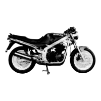
VALVE AND VALVE SPRING DISASSEMBLY
• Using special tools, compress the valve springs and remove
the two cotter halves 1 from valve stem.
% 09916-14510: Valve spring compressor
09916-14910: Valve spring compressor attachment
09916-84511: Tweezers
• Remove the valve spring retainer, inner spring and outer spring.
• Pull out the valve from the other side.
• Remove the valve stem seal and valve spring seat.
NOTE:
Removal of valves completes ordinary disassembling work. If valve
guides have to be removed for replacement after inspecting re-
lated parts, carry out the steps shown in valve guide servicing
(
!
3-27)
CYLINDER HEAD DISTORTION
• Decarbonize the combustion chambers.
Check the gasketed surface of the cylinder head for distortion
with a straightedge and thickness gauge, taking clearance read-
ing at several places indicated. If the largest reading at any posi-
tion of the straightedge exceeds the limit, replace the cylinder
head.
" Cylinder head distortion
Service Limit: 0.05 mm (0 002 in)
% 09900-20803: Thickness gauge
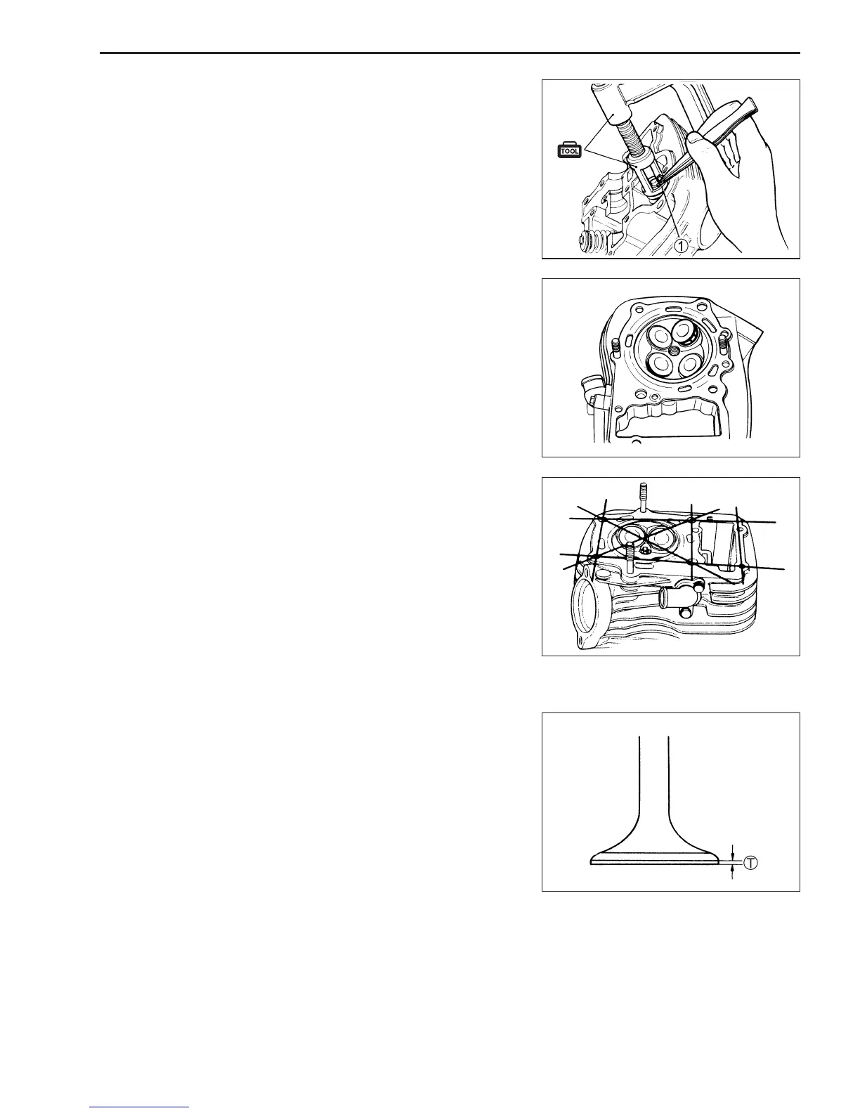
VALVE FACE WEAR
Visually inspect each valve for wear of its seating face. Replace
any valve with an abnorma ly worn face.
The thickness T decreases as the wear of the face advances.
Measure the thickness and, if the thickness is found to have been
reduced to the limit replace it.
" Valve head thickness
Service Limit T: 0.5 mm (0.02 in)
% 09900-20102: Vernier calipers
 Loading...