getting started
17
Synrad Firestar ti-Series operator’s manual
Mounting
2
Place Firestar on the mounting surface so that slots “A” and hole “B” on the base plate line up with
the tapped holes in the mounting surface.
3
Insert 1/4–20 × 5/8" UNC capscrews through Firestar’s base plate into the threaded holes of the
mounting surface. Turn the screws by hand until the threads engage.
4
Tighten all three capscrews to a torque of 5 ft lb
f
(7 N m). Do not exceed a torque of 6 ft lb
f
(8 N m)
as the base plate may be damaged.
Fasten from below
To fasten your Firestar ti-Series laser to a mounting surface from below, perform the following steps:
1
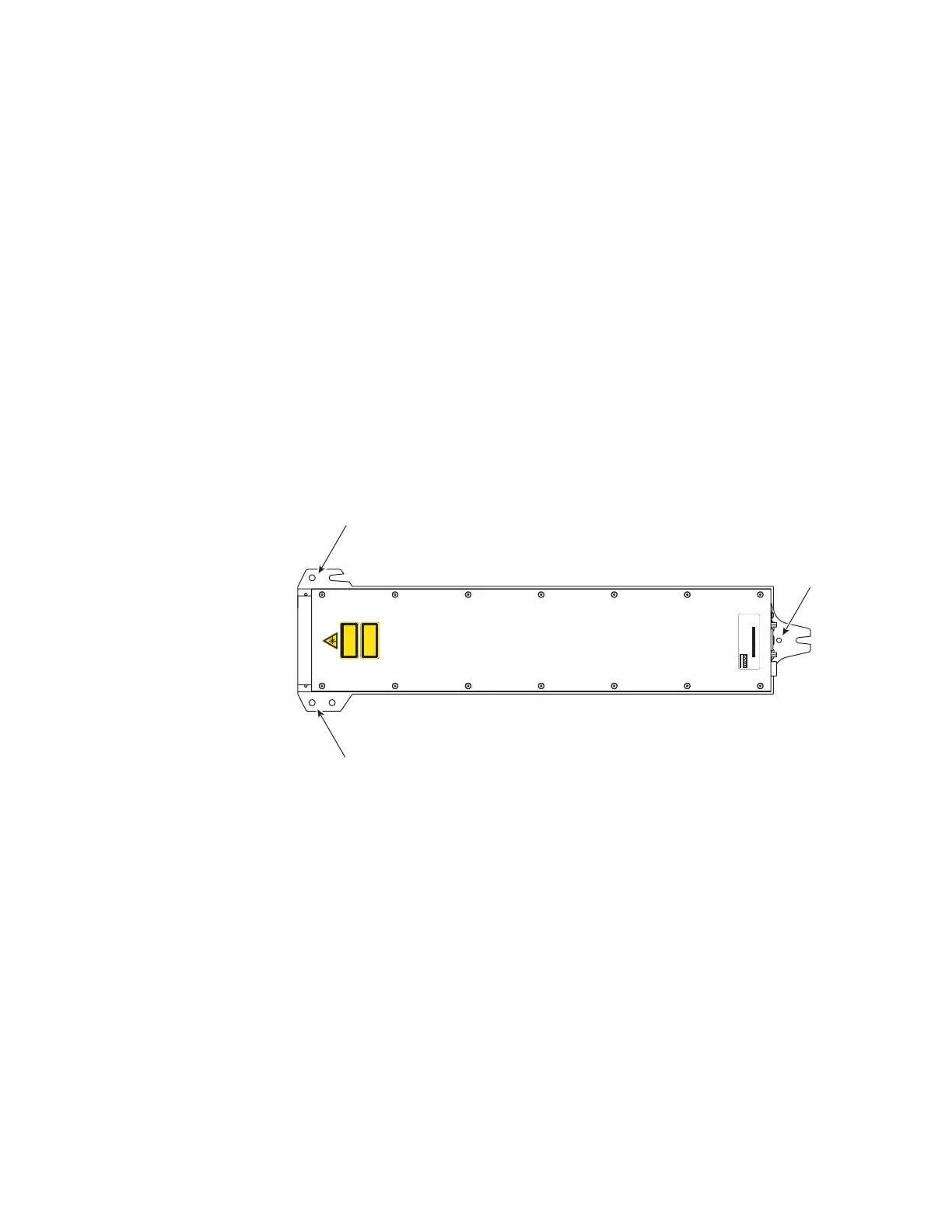
Refer to the appropriate outline and mounting drawing for dimensions and then drill three 0.261"
(6.6 mm) diameter holes into your mounting surface. Hole locations should correspond to the
threaded holes labeled “C” shown in Figure 1-3.
Figure 1-3 Fasten from below
2
Place Firestar on the mounting surface so that the threaded holes on the base plate (labeled “C” in
Figure 1-3) line up with the 0.261" (6.6 mm) holes drilled through the mounting surface.
3
Insert 1/4–20 × 5/8" UNC capscrews through the mounting surface into the threaded holes of
Firestar’s base plate. Turn the screws by hand until the threads engage.
4
Tighten all three capscrews to a torque of 5 ft lb
f
(7 N m). Do not exceed a torque of 6 ft lb
f
(8 N m)
as the base plate may be damaged.
INVISIBLE LASER RADIATION
AVOID EYE OR SKIN EXPOSURE TO
DIRECT OR SCATTERED RADIATION
CLASS 4 LASER PRODUCT
EN-60825-1, 1993
400 WATTS MAX
10200-10800 nm
MODEL #: FSTI60SAB
SERIAL #: TI60234080181
TESTED AT: 48V MFG: January 21, 2009
This laser component does not comply with standards for complete
laser products as specified by 21 CFR 1040.10 or IEC 60825-1.
SYNRAD, Inc. 4600 Campus Place, Mukilteo WA 98275 425.349.3500
C
C
C
Top View
(ti60 Air-Cooled Model)

 Loading...