operation
23
Synrad Firestar ti-Series operator’s manual
Controls and indicators
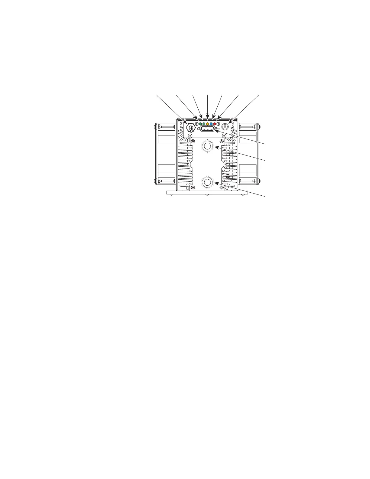
ti-Series rear panel
Figure 2-2 ti-Series rear panel controls and indicators
1
DC Power Cables – receives +48 VDC from the DC power supply. Firestar ti-Series DC power cables
are manufactured from #10 AWG wire and measure 1 meter (42 inches) in length.
2
INT (Remote Interlock) Indicator – illuminates green to indicate that a remote interlock circuit is
closed and that lasing may be enabled. The INT indicator is red and lasing is disabled if the interlock
input is open.
3
TMP (Temperature) Indicator – illuminates green to indicate that laser temperature is within limits
and that lasing may be enabled. The TMP indicator is red and lasing is disabled if the laser’s tem-
perature rises above safe operating limits.
4
RDY (Ready) Indicator – illuminates yellow when the laser is enabled, indicating that, after a five-
second delay, lasing will begin when a PWM Command signal is applied.
5
SHT (Shutter) Indicator – illuminates blue to indicate that a Shutter Open Request signal is con-
nected to the User I/O port and lasing may be enabled. When a Shutter Open Request signal is
applied, there is a five-second delay until PWM inputs are recognized.
6
LASE Indicator – illuminates red to indicate that the laser is actively lasing. The LASE indicator is
off when tickle pulses are being generated and illuminates red when PWM Command signal pulses
are long enough to produce laser output.
7
Keyswitch (Keyswitch models only) – enables/disables operation of the laser. Firestar is enabled when
the Keyswitch is turned to the ON position. Turn the Keyswitch OFF to disable lasing.
8
USER I/O Connector – provides a connection point for auxiliary output power as well as input and
output signals. Refer to User I/O connections in the Technical Reference chapter for pinouts and
signal descriptions.
9
WATER IN Port (water-cooled models only) – labeled IN, this connection provides the cooling
water inlet to Firestar’s water-cooling system.
10
WATER OUT Port (water-cooled models only) – labeled OUT, this connection provides the cooling
water outlet from Firestar’s water-cooling system.
ON
USER I/O
INT
TMP RDY SHT LASE
(Fan-Cooled ti60 Shown)
1
2
4
5
3
6
8
7
9
10
OFF

 Loading...