EasyManuals Logo

Synrad Firestar TI Series User Manual

Synrad Firestar TI Series
112 pages
To Next Page IconTo Next Page
To Previous Page IconTo Previous Page
Page #72 background imageLoading...
Page #72 background image
technical reference
322 Synrad Firestar ti-Series operator’s manual
User I/O connections
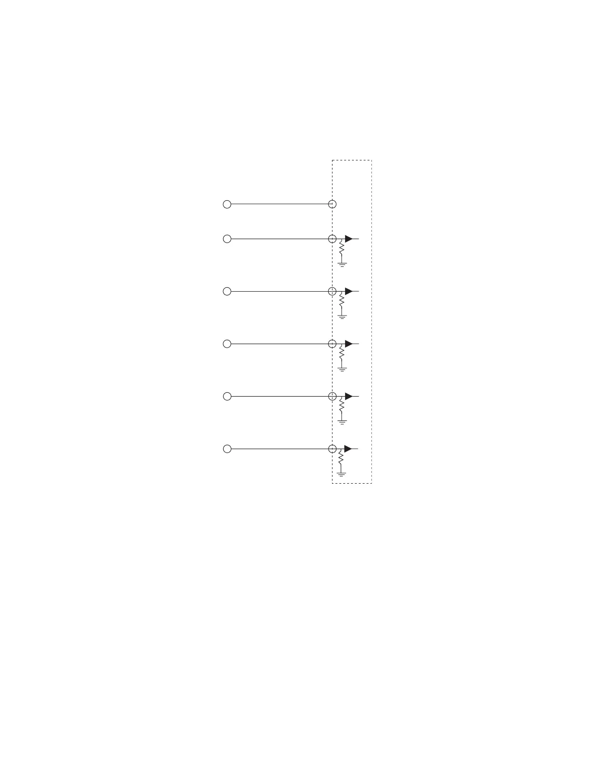
Figure 3-17 illustrates how Firestar’s outputs can drive the DC Input Module of a Programmable Logic
Controller (PLC). By supplying voltage (+VDC) to Pin 13, Output Common, each Firestar output is
independently switched to activate individual PLC inputs.
Figure 3-17 Firestar output driving PLC input module
USER I/O PINS
PLC
DC
INPUT
MODULE
(13) OUTPUT COMMON
(6) LASER ACTIVE
(7) OVER TEMPERATURE
(8) LASER READY
(14) SHUTTER OPEN
(15) INTERLOCK OPEN
V+
(+5–24V)

Table of Contents

Other manuals for Synrad Firestar TI Series

Questions and Answers:

Question and Answer IconNeed help?

Do you have a question about the Synrad Firestar TI Series and is the answer not in the manual?

Synrad Firestar TI Series Specifications

General IconGeneral
BrandSynrad
ModelFirestar TI Series
CategoryMedical Equipment
LanguageEnglish

Related product manuals