getting started
113
Synrad Firestar ti-Series operator’s manual
Connecting
Electrical connections
The following procedures describe how to complete electrical connections to ti-Series lasers. Firestar ti-
Series DC power cables are manufactured from #10 AWG wire and measure 1 meter (42 inches) in length.
DC power supply
Note: The negative (–) side of the DC input to the laser is internally connected so that the laser chas-
sis serves as DC power ground. You should isolate the laser’s DC power supply so that the only
grounded connection is at the laser. Alternatively, you can mount the laser chassis on an insulat-
ing pad or film in order to electrically isolate the laser when other equipment is grounded to the
laser’s DC power supply.
Caution
possible
equipment
damage
Do not reverse polarity when connecting DC power cables to your
DC power source. Reversed DC polarity will damage the ti-Series’s
internal RF and control board circuitry. Carefully follow the direc-
tions below to ensure that DC cable leads are properly connected to
the correct DC output terminals.
Firestar ti60 lasers require a DC power supply capable of supplying 48 VDC at 18 A minimum while
Firestar ti100 lasers require a 48 VDC at 35 A minimum. We recommend the SYNRAD DC-48 DC power
supply, which can provide a maximum of 40 A at 48 VDC. AC input requirements for the DC-48 supply
are 180–264 VAC, single-phase (1Ø), 9.3 A max (@ 230 VAC), 47–63 Hz. To connect the DC- 48 supply,
refer to Figure 1-6 and perform the following steps:
AC Line (Black/Brown) to ‘L’
AC Neutral (White/Blue) to ‘N’
AC Ground (Green)
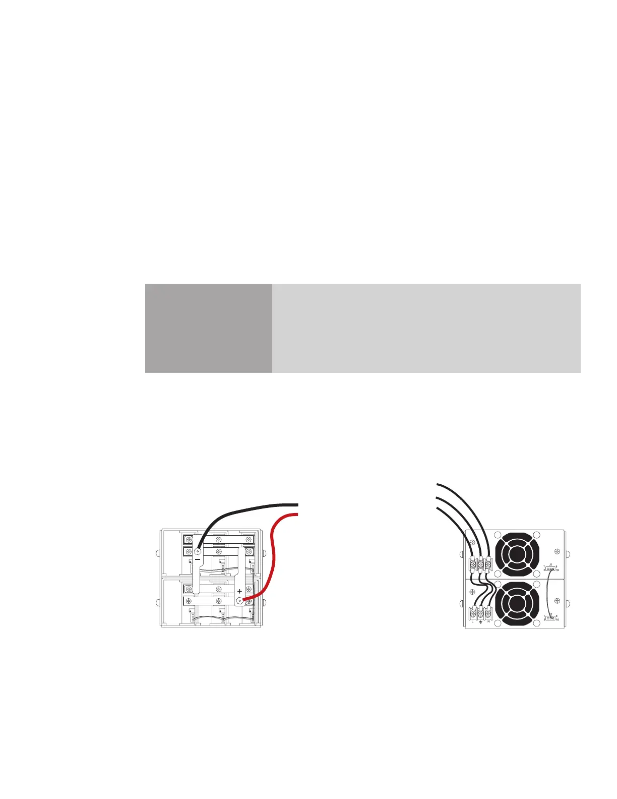
Front View
Black (ground) wire from laser
to (–) Negative post
Red (power) wire
from laser to (
+)
Positive post
Rear View
Figure 1-6 DC-48 DC power supply
1
Verify that input AC power to the DC power supply is physically locked out or disconnected.
2
Locate the 48 VDC output terminals on the power supply’s output section and connect the black (–)
DC power cable from the laser to the negative (–) output terminal.
3
Connect the red (+) DC power cable from the laser to the positive (+) 48 VDC output terminal.

 Loading...