technical reference
324 Synrad Firestar ti-Series operator’s manual
DB-9 connections
(SA models only)
Pin Function Description
5 Fan Power Return
This connection provides a return (ground) path for Pin 4 and Pin 8 (Fan Power, +48 VDC).
Pin 5 and Pin 9 (Fan Power Return) can only sink a combined current of 1.0 A total. Internal
circuitry allows the laser to control fan speed based on the laser’s output power and chassis tem-
perature. See 48 VDC fan speed control for detailed information.
6, 7 Signal Ground
Pin 6 and Pin 7 provide a return (ground) path for Pin 2 (Shutter Switch), Pin 3 (+5 VDC Auxil-
iary Power), or Pin 5/Pin 8 (Fan Power, +48 VDC) when fan speed control is not required. Pin 6
and Pin 7, Signal Ground, are the only DB-9 pins connected to chassis ground. Do not use these
pins if DC power is supplied from an external customer-supplied DC power source.
8 Fan Power, +48 VDC
This output provides +48 VDC for powering a customer-supplied cooling fan. The Fan Power,
+48 VDC output (Pin 8) is sourced directly from the user’s 48 VDC power supply and is protected
by a 1.1 A self-resetting fuse. Pin 4 and Pin 8 can only source a combined current of 1.0 A total.
9 Fan Power Return
This connection provides a return (ground) path for Pin 4 and Pin 8 (Fan Power, +48 VDC).
Pin 5 and Pin 9 (Fan Power Return) can only sink a combined current of 1.0 A total. Internal
circuitry allows the laser to control fan speed based on the laser’s output power and chassis tem-
perature. See 48 VDC fan speed control for detailed information.
48 VDC fan speed control
The side-mounted DB-9 connector on SA model lasers has internal circuitry that controls fan speed based
on the laser’s output power and chassis temperature. At tickle, or very low PWM duty cycles, cooling fans
run at reduced speed to minimize noise; at higher PWM duty cycles, fan speed increases to match the cool-
ing rate to power output. Fan speed is controlled by pulse width modulation (PWM) of the Fan Power
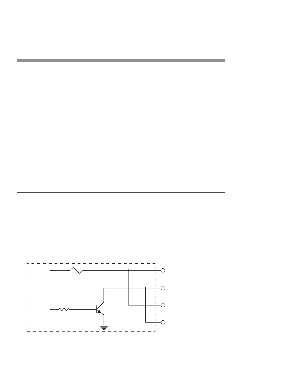
Return lines (Pin 5/Pin 9) as shown in Figure 3-19.
Figure 3-19 Internal fan speed control circuitry
ti-Series Fan Control Output Section
(4) FAN POWER, +48 VDC
(5) FAN POWER RETURN
(8) FAN POWER, +48 VDC
(9) FAN POWER RETURN
DB-9 PINS
Q1
R1
PWM FAN
CONTROL
SIGNAL
48 VDC
1.1 A FUSE

 Loading...