12—9
Residual‐current‐operatedprotectivedevices
Terminal
Function / connection
L1, N, PE
Mains connection for 1 ~ types (observe the line voltage indicated
rating plate).
L1, L2, L3, PE
Mains connection for 3 ~ types (observe the line voltage indicated
rating plate).
11, 14
Relay output “K1” for fault indication.
*
•
For operation the relay is energized,
connections
“11”
and
“14”
are bridged. For fault the relay is de-energized (
Diagnostics / faults).
•
When switching off via enable (D1 = Digital In 1), the relay remains
energized.
E1, GND
Analog input for setting speed via 0 - 10 V or PWM signal
*
10V
Voltage supply for speed setting by 10 kΩ potentiometer.
24V
Voltage supply for external devices.
D1, +24V
Digital input for enable.
*
•
Device
“ON”
for closed contact.
•
Controller
“OFF”
with opened contact.
*Functionforstandardfactorysetting,differentpresettingpossible.
UL:Input(Line)
•
Cu connection leads with the following specifications must be employed:
– Minimum insulation temperature of 80 °C
– Terminal tightening torque for field block (L1, N, and/or L1, L2, L3) of 5 - 7 Lb In.
(Exception: spring-cage terminal for motor size "G" @ line voltage 3 ~ 200...240 V) – Terminal tightening
torque of 4.5 Lb In for field block (K1).
– Terminal tightening torque of 4.5 Lb In for all other field blocks.
– Terminal tightening torque of 2.2 Lb In for add-on modules.
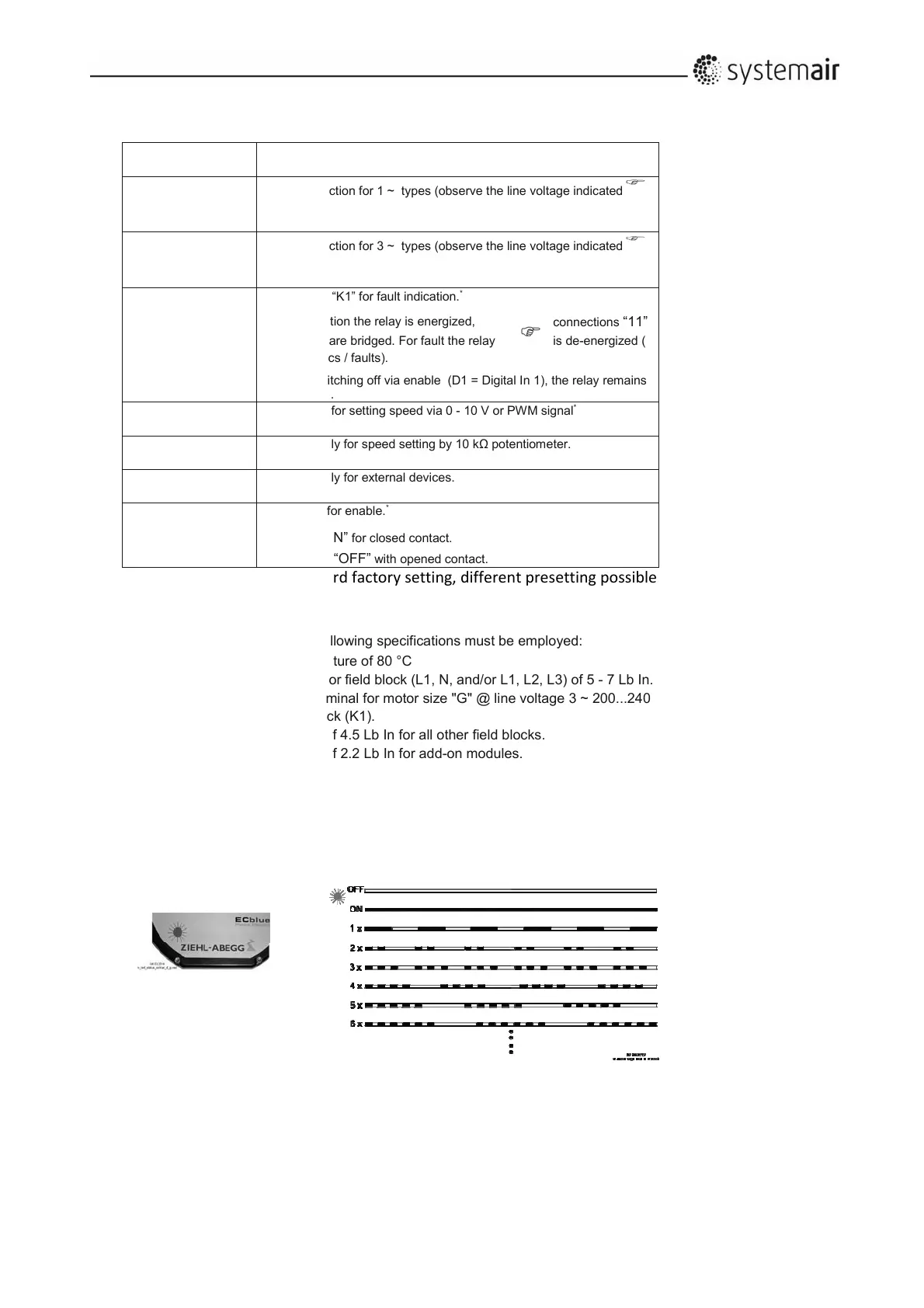
12.5.2Diagnostic/faults
Status Out with flash code