9—1
Annex9. Speedcontrolforrotorandassemblyofdividedrotor
9.1Speedcontrol
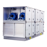
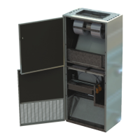
Thecabinetwiththespeedcontrolsystemfortherotorisinstalledbehindtheinspectiondoorintherotor
section.
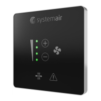
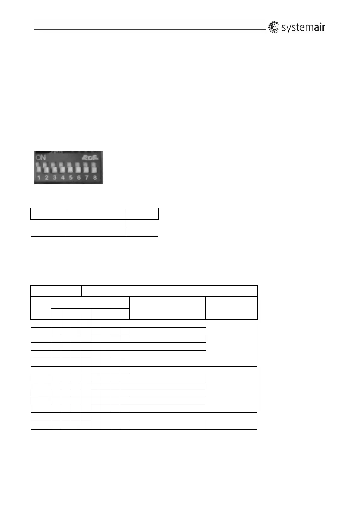
Thecabinetcontainsthespeedcontrollerwithallcomponents,terminalblocks,LEDdisplayingthe
operationmode,thedualpositionDIPswitchwith8slidingleversforprogrammingtherotormotorsignal
andabuttonfortheactivationofthetestmode.
Throughthedifferentcombinationsofthe8slidingleversofthisdualpositionDIPswitch,thecorrectsignal
isavailableforthe3differentmotorsusedforthe14sizesofairhandlingunits.Theslidingleversareset
and
thefunctionischecke datthefactory.Thepositionsoftheleversappearfromthetablesbelow.
9.1.1Selectionofcorrectsignalviathe8DIPswitchlevers
The8DIPswitchlevers
Position Function Code
Up Active=ON 1
Down Deactivated=OFF 0
Thefactorysetsthepositionsofthe8DIPswitchleversforthemaximumof12revolutionsperminute
forstandardtemperatureexchangersandforhygroscopicexchangers.ThepositionofeachDIPswitch
leverisshownbelow.
Rotor12rpm Condensation/temperature(ST),SorptionHybrid(SH)
DV
PositionofDIPswitches Diameterofpulleyfor
rotorsfromHoval
Motortype
1 2 3 4 5 6 7 8
10 0 0 0 0 0 0 0 0 50
90TYD‐S214‐M
15 0 0 0 0 0 0 0 0 50
20 1 0 0 0 0 0 0 0 50
25 0 0 0 0 0 0 0 0 65
30 1 0 0 0 0 0 0 0 65
40 1 0 0 0 0 0 0 0 65
50 0 1 0 0 0 0 0 0 85
120TYD‐S214‐M
60 0 1 0 0 0 0 0 0 95
80 0 1 0 0 0 0 0 0 106
100 0 1 0 0 0 0 0 0 106
120 1 1 0 0 0 0 0 0 106
150 1 1 0 0 0 0 0 0 106
190 1 0 1 0 0 0 0 0 132
120TYD‐S214‐L
240 1 0 1 0 0 0 0 0 140