11
d.Generaldescriptions,dangersandwarnings
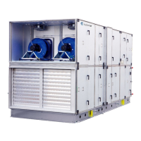
TIMEandDVairhandlingunitsareorderspecificmachinesavailableinthousandsofdifferent
configurations.Onlyafewexamplesofmachineconfig urationsaredescribedbelow.
Theairhandlingunitsareintendedforthetransportandtreatmentofairbetween‐40°Cand+40°C
Theunitsareexclusivelyfor
comfortventilation.
Maintenanceoftheunitsmustbecarriedoutbyskilledtechnicians.
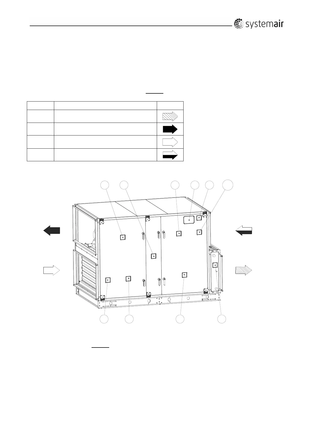
Onthedrawingbelow,arighthandunitisshownbecausetheinspectiondoorsaremountedontheright
handsideoftheunitwhenlookedindirectionofSUPPLYairflow.Theunitbelowiswithrotary
heat
exchanger.
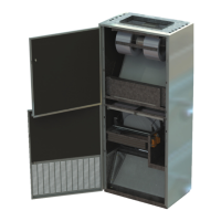
Position Description
S
mbol
A
Connection,supplyair(totherooms)
B
Connection,exhaustair
C
Connection,outdoorairin
D
Connection,extractair(fromtherooms)
d.1Overviewviapictogramsontheinspectionsideoftheunit
Thisisarighthandunitbecausetheinspectiondoorsaremountedontherighthandsideoftheunitwhen
lookingindirectionoftheSUPPLYairflow.
2
53
87
4
1
6
A
B
C
D
9 10