9—5
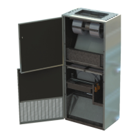
Connectionofcablestotheterminalsontheboard
Terminal Connection
1 Earth‐supply
2 Earth‐supply
3 Fase
supply
4 Neutral
supply
5
Rotorturnsupwardsseenfrominspection
side.
Terminal5=wire1
Terminal6=wire2
Terminal7=wire3
Rotorturndownwardsseenfrominspection
side.
Terminal5=wire2
Terminal6=wire1
Terminal7=wire3
6
7
8 Earthforrotormotor
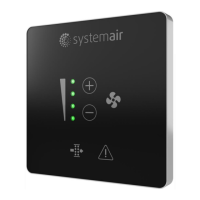
Test
SetDIPswitch4inposition
ON
andpressthebuttonfortest.Thesignaliscontrolledbythe
potentiometeratconstantspeedandnotbyanysignalfromthecontrol system.
Adjust
IsactivatedbysettingDIPswitch4atOFFandDIPswitch5atON.Herebythemaximum
revolutionscanbeadjustedbetween50and100%bythepotentiometer.Usuallythefactory
settingisOK,butwiththispotentiometerthemaximumrevolutionscanbereducedor
increased.
9 Alarmsignal
COM(common)
10 Alarmsignal
Relayisnormallyclosed(thisisusedbythecontrolsystemfromSystemair)
11 Alarmsignal
Relayisnormallyopen(thisisno
usedbythecontrolsystemfromSystemair)
12 Controlsignalinputis0‐10voltDC
13 Controlsignalinput
ground
14 Rotorguard
(blackcablefromrotorguardfromSystemair)
15 Rotorguard
(bluecablefromrotorguardfromSystemair)
16 Rotorguard
(browncablefromrotorguardfromSystemair)
17 ForBUSsignal
RS485
A(greenwirefromSystemaircontrolsystem)
18 ForBUSsignal
RS485
B(yellowwirefromSystemaircontrolsystem)
19 ForBUSsignal
ground(whitewirefromSystemaircontrolsystem)