Taco® SKV
16
302-365, Effective: June 5, 2017
© 2017 Taco, Inc.
Control Terminal Types
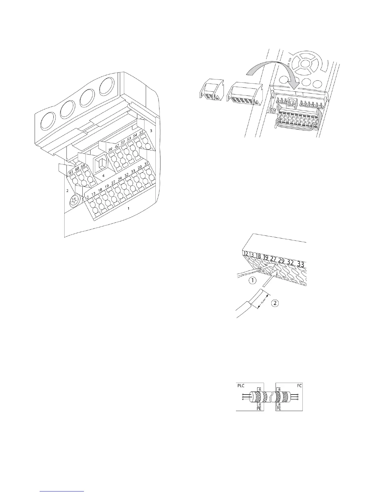
Figure 8-14 shows the removable adjustable frequency
drive connectors.
Figure 8-14: Control Terminal Locations
• Connector 1 provides four programmable digital
inputs terminals, two additional digital terminals pro-
grammable as either input or output, a 24V DC termi-
nal supply voltage, and a common for optional
customer supplied 24V DC voltage.
• Connector 2 terminals (+)68 and (-)69 are for an RS-
485 serial communications connection.
• Connector 3 provides two analog inputs, one analog
output, 10V DC supply voltage, and commons for the
inputs and output.
• Connector 4 is a USB port available for use with the
MCT-10 Set-up Software.
• Also provided are two Form C relay outputs that are
in various locations depending upon the adjustable
frequency drive configuration and size.
Wiring to Control Terminals
Control terminal connectors can be unplugged from the
adjustable frequency drive for ease of installation, as
shown in Figure 8-15.
Figure 8-15: Unplugging Control Terminals
1.Open the contact by inserting a small screwdriver
into the slot above or below the contact, as shown
in Figure 8-16.
2.Insert the bared control wire into the contact.
3.Remove the screwdriver to fasten the control wire
into the contact.
4.Ensure the contact is firmly established and not
loose. Loose control wiring can be the source of
equipment faults or less than optimal operation.
Figure 8-16: Connecting Control Wiring
Using Shielded Control Cables
Correct Shielding
The preferred method in most cases is to secure control
and serial communication cables with shielding clamps
provided at both ends to ensure best possible high fre-
quency cable contact.